
Hemisphere monitoring equipment shaft structure

A technology of monitoring equipment and rotating shaft structure, which is applied in the direction of mechanical equipment, supporting machines, machine tables/supports, etc. It can solve the problems of inaccurate control of length, inability to flexibly adjust the monitoring angle of the shaft ball, inconvenient use of consumers, etc., to achieve wiring And subsequent adjustments are flexible, practical and novel, and the effect of product wiring adjustment is orderly

Active Publication Date: 2017-11-10
厦门星纵物联科技有限公司
View PDF6 Cites 0 Cited by
  • Summary
  • Abstract
  • Description
  • Claims
  • Application Information

AI Technical Summary

Problems solved by technology

In this process, the cable must be connected first before the ball bracket can be locked on the base, which is extremely inconvenient for the entire product assembly and consumer use, and the pre-installation required for the cable The remaining length cannot be accurately controlled. The cable must be connected first before the pivot ball bracket can be locked on the base. If the length is too short, the pivot ball cannot flexibly adjust the monitoring angle, or even the pivot ball is stuck and cannot be adjusted. and subsequent adjustments will cause inconvenience

Method used


Image

  • Hemisphere monitoring equipment shaft structure
  • Hemisphere monitoring equipment shaft structure
  • Hemisphere monitoring equipment shaft structure

Examples


Embodiment Construction

[0015] The present invention will be further described below in conjunction with the accompanying drawings and specific embodiments.

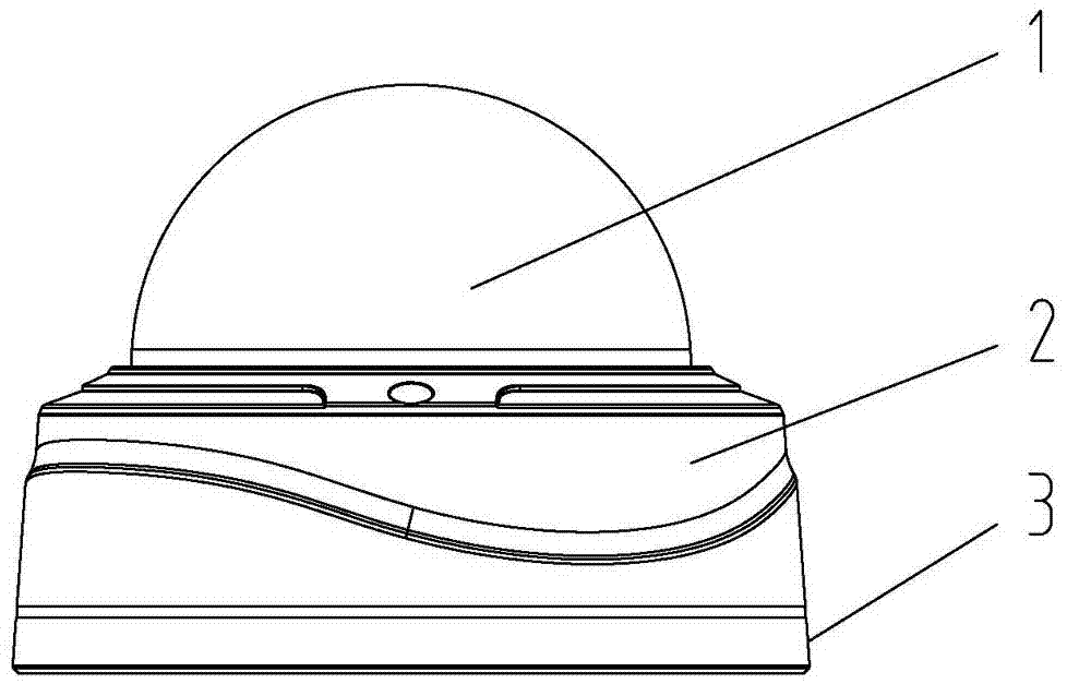
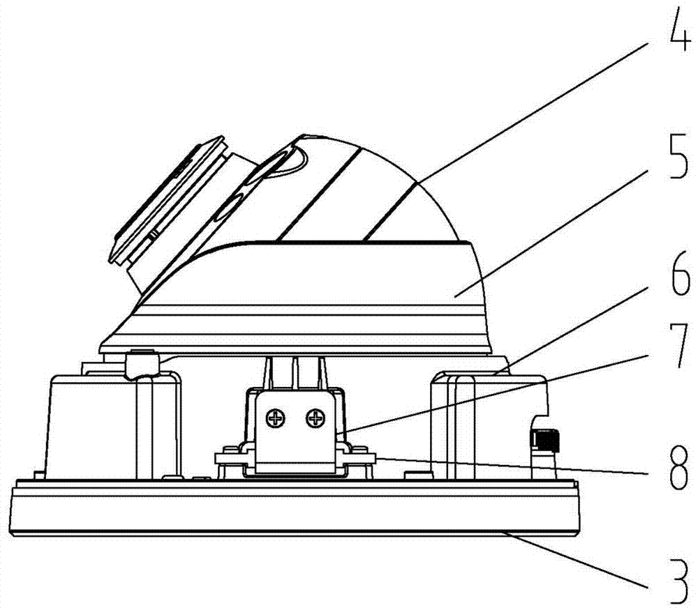
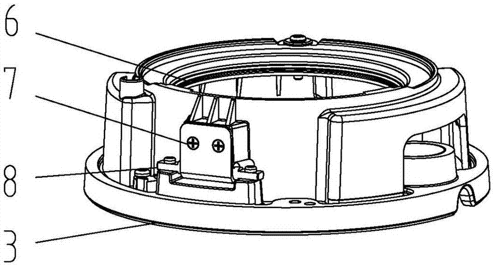
[0016] Such as Figure 1 to Figure 4 As shown, the rotating shaft structure of the hemispherical monitoring device of the present invention includes a hemispherical cover 1, a housing 2 and a base 3, and the inside of the housing 2 is provided with a shaft ball assembly 4, a shaft ball cover 5 and a shaft ball bracket 6, and the The shaft ball assembly 4 is fixed on the shaft ball bracket 6 through the shaft ball cover 5, and the outer side of the shaft ball bracket 6 is provided with a shaft sleeve 7, and the two sides of the shaft sleeve 7 are provided with a reversible rotating shaft 8 for fixing the base 3 , the rotating shaft 8 is in the shape of a "one", and the rotating shaft 8 is fixed to the base 3 by screws. The base 3 is provided with a base plate 9, the base plate 9 is connected to a terminal wire 11 through a female socket 10, the...


PUM


Abstract

The invention relates to a rotating shaft structure of hemispherical monitoring equipment. The rotating shaft structure comprises a hemispherical cover, a shell and a base, wherein a shaft sphere component, a shaft sphere cover and a shaft sphere bracket; the shaft sphere component is fixedly arranged on the shaft sphere bracket via the shaft sphere cover; a shaft sleeve is arranged at the outer side of the shaft sphere bracket; reversible rotating shafts for fixing the base are arranged at the two sides of the shaft sleeve; a base plate is arranged on the base and is connected with a terminal wire via a female socket; the other end of the terminal wire is connected with a waterproof joint. The rotating shaft structure disclosed by the invention is capable of mainly solving the problem caused by a traditional assembly way of the hemispherical monitoring equipment; the overall assembly process is convenient; a product is enabled to be better in practicability and novelty; by the design of the rotating shaft between the base and the shaft sphere bracket, wire connection and subsequent regulation of the overall product can be more flexible; the preset length of wire arrangement can be accurately controlled; moreover, the overall wiring of the product is more methodic and orderly.

Description

technical field [0001] The invention relates to the field of monitoring equipment, in particular to a hemispherical monitoring equipment rotating shaft structure. Background technique [0002] In the traditional hemispherical monitoring equipment, the camera is first installed on the axis ball, and then the cable connected to the camera is connected, and the axis ball is locked on the base through the axis ball bracket. In this process, the cable must be connected first before the ball bracket can be locked on the base, which is extremely inconvenient for the entire product assembly and consumer use, and the pre-installation required for the cable The remaining length cannot be accurately controlled. The cable must be connected first before the pivot ball bracket can be locked on the base. If the length is too short, the pivot ball cannot flexibly adjust the monitoring angle, or even the pivot ball is stuck and cannot be adjusted. And subsequent adjustments will cause incon...

Claims


Application Information

Patent Timeline
Patent Type & Authority Patents(China)
IPC IPC(8): F16M11/22
CPCF16M11/22F16M2200/00
Inventor 王跃拼赖其
Owner 厦门星纵物联科技有限公司
Learn More