Wire arrangement device

A wire arrangement and wire structure technology, applied in the field of diode processing, can solve problems such as low efficiency and troublesome operation, and achieve the effects of convenient operation, good effect, and avoiding pin drop

Active Publication Date: 2019-04-12
ANHUI LONGXINWEI TECH CO LTD
View PDF5 Cites 1 Cited by
  • Summary
  • Abstract
  • Description
  • Claims
  • Application Information

AI Technical Summary

Problems solved by technology

[0005] The present invention intends to provide a cable arrangement device to solve the problem in the prior art that the pins that have not been successfully arranged need to be manually collected and re-arranged, and the operation is cumbersome and the efficiency is not high.

Method used


Image

  • Wire arrangement device
  • Wire arrangement device
  • Wire arrangement device

Examples


Embodiment Construction

[0024] The following is further described in detail through specific implementation methods:

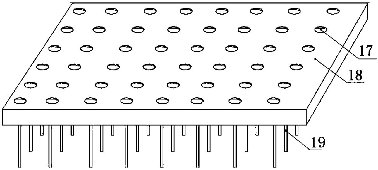
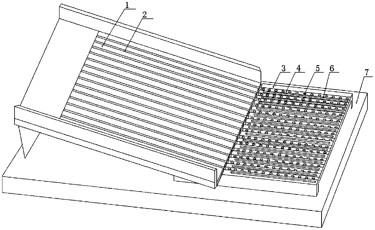
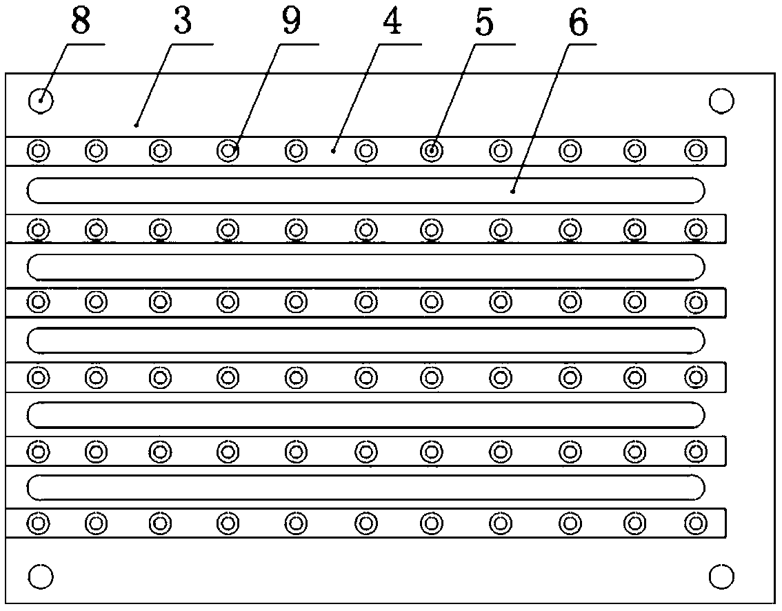
[0025] The reference signs in the drawings of the description include: feeding plate 1, feeding channel 2, first receiving plate 3, receiving trough 4, socket 5, leaking hole 6, frame 7, connecting hole 8, air bag 9, Connecting rod 10, second material receiving plate 11, conduit 12, piston 13, piston rod 14, air chamber 15, handle 16, cable hole 17, cable plate 18, pin 19.

[0026] Such as figure 2 As shown, a cable arrangement device of the present invention includes a frame 7, on which a feeding plate 1 is obliquely installed, and the feeding plate 1 is connected with a driving mechanism for driving its vibration. In this embodiment, the driving mechanism adopts Shanghai Zhichuan Company NETTER vibrator. The feeding plate 1 is provided with several feeding passages 2 for conveying the pins 19, the feeding passages 2 are arranged along the length direction of the feeding board 1,...


PUM


Abstract

The invention relates to the technical field of diode processing, in particular to a wire arrangement device. The wire arrangement device comprises an obliquely-arranged feeding plate, wherein the feeding plate is connected with a driving mechanism for driving the feeding plate to vibrate, a plurality of feeding channels are arranged on the feeding plate, a material receiving mechanism for arranging pins is detachably arranged at the lower end of the feeding plate, a wiring mechanism has a multilayer structure, and each layer is respectively provided with a wire arrangement structure for collecting and rearranging the redundant pins. According to the scheme of the invention, the problem that the pins that are not successfully arranged need to be manually collected for wire re-arrangement,and troublesome operations and low efficiency are caused in the prior art can be solved.

Description

technical field [0001] The invention relates to the technical field of diode processing, in particular to a cable arrangement device. Background technique [0002] A diode is an electrical component that only allows current to flow from a single direction. The diode has a PN junction and two pins. During processing, the two pins are welded on both sides of the PN junction, and finally packaged. [0003] In order to facilitate operation, in the prior art, the diode pins are arranged in such as figure 1 On the shown wiring board 18, then add solder and PN junction in the wiring hole 17 of one of the wiring boards 18, and then buckle another piece of wiring board 18 upside down on the aforementioned wiring board 18, so that the two The wiring holes 17 of the two wiring boards 18 are buckled together, and finally the two wiring boards 18 are taken together for heating, so that the two pins 19 can be welded together. [0004] In the prior art, most of the pins are arranged on t...

Claims


Application Information

Patent Timeline
Patent Type & Authority Applications(China)
IPC IPC(8): H01L21/67H01L29/861
CPCH01L21/67121H01L21/67144H01L29/861
Inventor 赵凡奎许秀冬程志
Owner ANHUI LONGXINWEI TECH CO LTD
Why Eureka
Try Eureka