Full-automatic cross-flow fan blade shaft hole angle adjusting all-in-one machine

A technology of cross-flow fan blades and angle adjustment, which is applied to household components, home appliances, other household appliances, etc., can solve the problems of low efficiency, high production cost of cross-flow fan blades, and large labor consumption, and achieves convenient operation and reduces labor. Labor, the effect of improving production efficiency

Pending Publication Date: 2021-01-05
四川朗迪塑胶电器有限公司
View PDF0 Cites 1 Cited by
  • Summary
  • Abstract
  • Description
  • Claims
  • Application Information

AI Technical Summary

Problems solved by technology

[0005] The purpose of the present invention is to: for the manufacture of the existing cross-flow fan blades, manual operation is used to make the position of the shaft hole on the shaft sleeve assembly opposite to the space between the blades. In the whole process, the labor consumption is large and the efficiency is low. To solve the technical problem of high production cost of blades, a fully automatic cross-flow fan blade shaft hole angle adjustment machine is provided.

Method used


Image

  • Full-automatic cross-flow fan blade shaft hole angle adjusting all-in-one machine
  • Full-automatic cross-flow fan blade shaft hole angle adjusting all-in-one machine
  • Full-automatic cross-flow fan blade shaft hole angle adjusting all-in-one machine

Examples


Embodiment 1

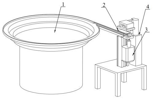
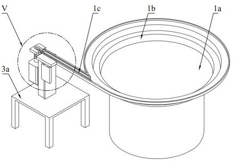
[0032] Such as Figure 1-5 As shown, a full-automatic all-in-one machine for adjusting the shaft hole angle of cross-flow fan blades, pour the shaft sleeve assembly 5 into the feeding device, adjust the operation program of the control system, press the start switch, and the feeding device 1 will put the shaft sleeve assembly 5 are sequentially arranged and transported to the discharge port, and the pushing device pushes the shaft sleeve assembly 5 at the position of the feed device discharge port into the lifting and steering device 3 in turn, and the lifting and steering device 3 moves vertically to push the shaft sleeve assembly 5 into In the clamping and positioning device 4, the clamping and positioning device 4 adjusts the angle of the shaft hole 51 of the shaft sleeve assembly 5 and then docks with the cross-flow fan blade in the injection mold. The control system controls the feeding device 1, the pushing device 2, and the lifting and steering device 3 Cooperating with...

Embodiment 2

[0037] Such as Figure 1-5 As shown, the fully automatic cross-flow fan shaft hole angle adjustment integrated machine of this embodiment has the same structure as that of Embodiment 1, the difference is that: the support 31 is also provided with a lifting mechanism 3b, and the first servo motor 3c Set on the lifting mechanism 3b.

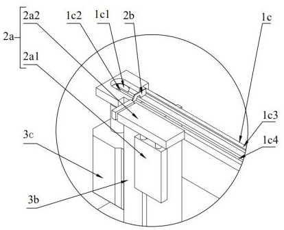
[0038] The fully automatic all-in-one machine for adjusting the shaft hole angle of cross-flow fan blades in this embodiment preferably adopts a photoelectric sensor 5 arranged on one side of the claw, so that when the lifting mechanism 3b drives the rotating rod 3c1 on the first servo motor 3c to pass through The through hole 22 at the tail end of the conveying guide rail 1c generates a control signal when the shaft sleeve assembly 5 is pushed up to cut off the photoelectric sensor signal in the claw, so that the first servo motor 3c starts to rotate, and the shaft sleeve assembly 5 is connected to the shaft sleeve assembly 5 under the action of g...

Embodiment 3

[0040] Such as Figure 1-5 As shown, the fully automatic cross-flow air blade shaft hole angle adjustment integrated machine of this embodiment has the same structure as that of Embodiment 2, the difference is that it also includes a pushing device 2, and the pushing device 2 is arranged on the conveying guide rail 1c- On the side, the pushing device 2 includes a first driving cylinder 2a and a blocking block 2b, and the first driving cylinder 2a includes a first telescopic cylinder 2a1 and a second telescopic cylinder 2a2 arranged on the first telescopic cylinder 2a1, The blocking block 2b is detachably connected to the telescopic rod of the second telescopic cylinder 2a2, the first telescopic cylinder 2a1 drives the second telescopic cylinder 2a2 to move in a direction perpendicular to the conveying guide rail 1c, and the second telescopic cylinder 2a2 drives The blocking block 2b moves along the conveying direction of the conveying guide rail 1c, and pushes the single sleev...


PUM


Abstract

The invention relates to the field of cross-flow fan blade machining equipment, in particular to a full-automatic cross-flow fan blade shaft hole angle adjusting all-in-one machine which comprises a control system, a feeding device, a pushing device, a lifting steering device and a clamping positioning device. The feeding device is used for arranging and conveying shaft sleeve assemblies; the pushing device is used for sequentially pushing the shaft sleeve assemblies on the feeding device into the lifting steering device; the lifting steering device is used for pushing the shaft sleeve assemblies into the clamping positioning device; the clamping positioning device is used for grabbing the shaft sleeve assemblies and adjusting the angles of shaft holes in the shaft sleeve assemblies; and the control system is used for controlling the feeding device, the pushing device, the lifting steering device and the clamping positioning device to operate in a linkage fit mode. The device is simplein structure and convenient to operate, the shaft hole in each shaft sleeve assembly is adjusted to be opposite to the vacancy between blades through integrated control, and in the whole process, thelabor of workers is greatly reduced, the production efficiency is improved, and the cost is saved.

Description

technical field [0001] The invention relates to the field of cross-flow fan blade processing equipment, in particular to a fully automatic cross-flow fan blade shaft hole angle adjustment integrated machine. Background technique [0002] Cross-flow fan blades are widely used in air-conditioning and other industries. There are cross-flow fan blades in the housing of the air conditioner. One end of the cross-flow fan blade is the supporting end face, and the other end is the connecting end face; There is a motor on one side of the supporting seat and the connecting end surface; the supporting end surface is movably arranged on the supporting seat through the supporting rotating shaft, and the connecting end surface is provided with a shaft sleeve assembly. The shaft sleeve of the sleeve assembly is provided with a shaft hole, and the output shaft of the motor passes through the shaft hole and is fixed with screws. Since the shaft sleeve is located Because it needs to be exten...

Claims


Application Information

Patent Timeline
Patent Type & Authority Applications(China)
IPC IPC(8): B29C45/14B29L31/08
CPCB29C45/14008B29L2031/082
Inventor 高文铭
Owner 四川朗迪塑胶电器有限公司
Why Eureka
Try Eureka