Self-arrangement cable winding and unwinding device for mechanical and electrical installation

A technology for rewinding, unwinding and installation, which is applied in the direction of transportation and packaging, conveying filamentous materials, thin material processing, etc. Ingenious, easy to operate, easy to get the effect of equipment

Inactive Publication Date: 2018-11-23
黄惠珍
View PDF5 Cites 1 Cited by
  • Summary
  • Abstract
  • Description
  • Claims
  • Application Information

AI Technical Summary

Problems solved by technology

[0003] At present, the cable winding devices used in large-scale electromechanical equipment all use electromechanical joints for cable winding, but there are still some problems in the winding process, such as the cables cannot be evenly wound on the winding roller during the winding process In order to avoid cable entanglement, some winders will be equipped with guide devices at present, but most of the existing guide devices have complex structures and are very inconvenient to operate

Method used


Image

  • Self-arrangement cable winding and unwinding device for mechanical and electrical installation
  • Self-arrangement cable winding and unwinding device for mechanical and electrical installation
  • Self-arrangement cable winding and unwinding device for mechanical and electrical installation

Examples


Embodiment 1

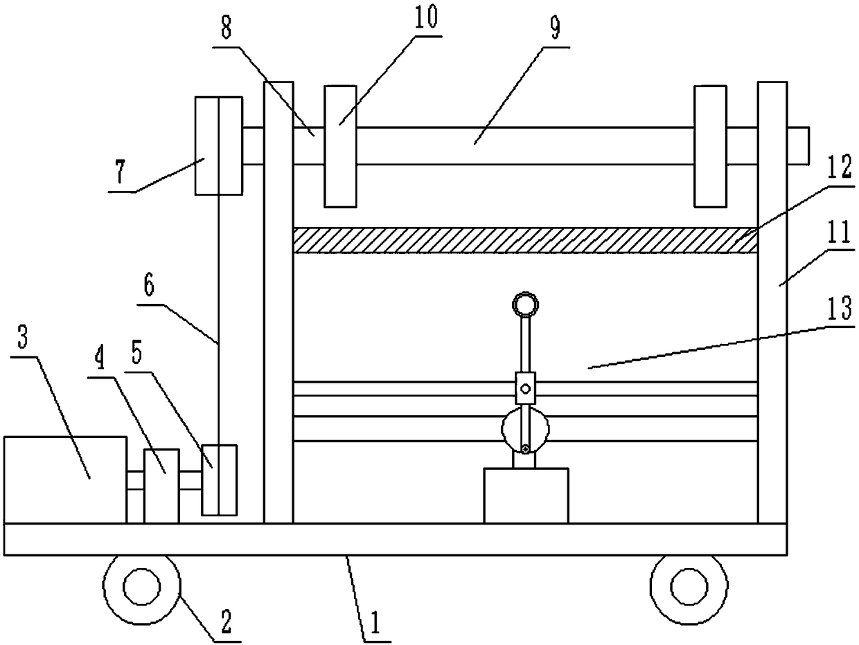
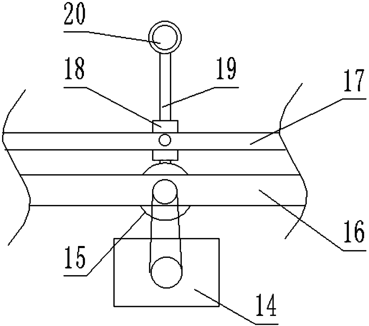
[0022] see Figure 1-2 , a self-arranging cable rewinding and unwinding device for electromechanical installation, comprising a vehicle frame 1, a support 11, a bidirectional motor 3 and a rewinding and unwinding roller 9, the support 11 is located above the vehicle frame 1, and the support 11 is arranged in parallel with each other And form vertical boards perpendicular to each other with the vehicle frame 1, the two ends of the rewinding and unwinding roller 9 are provided with a rotating shaft 8 that is clamped and installed with it, and the rotating shaft 8 is inserted on the support 11 and is connected with the support 11 in rotation. A guide 13 is provided below the rewinding and unwinding roller 9; the guide 13 includes an adjustment motor 14 fixed on the upper plane of the vehicle frame 1, a first cross bar 16 and a second cross bar 17 arranged in sequence above the adjustment motor 14, The output shaft of the adjustment motor 14 is arranged along the horizontal direct...

Embodiment 2

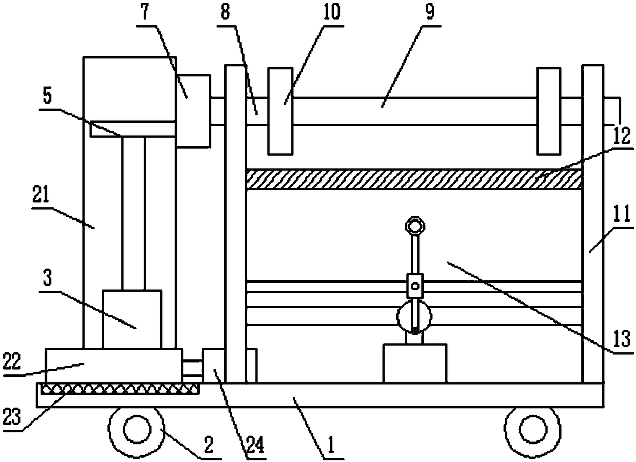
[0030] Such as image 3 As mentioned above, the difference from Embodiment 1 is that the bidirectional motor 3 is located in a motor box 21, and the output shaft of the bidirectional motor 3 is arranged vertically, and the driving wheel 5 is fixed on the top of the output shaft of the bidirectional motor 3 , an opening is provided on the side of the motor case 21, and the side opening of the motor case 21 is larger than the size of the driven wheel 7, a chute 23 is provided on the top surface of the vehicle frame 1, and a sliding base that is slidably connected to it is provided in the chute 23 22, the motor box 21 is fixed on the upper plane of the sliding base 22, and a hydraulic cylinder 24 is also provided on the top surface of the vehicle frame 1, and the output end of the hydraulic cylinder 24 is provided with a telescopic rod fixedly connected to the side of the motor box 21; When performing rewinding and unwinding work, the hydraulic cylinder 24 drives the motor box 21...


PUM


Abstract

The invention discloses a self-arrangement cable winding and unwinding device for mechanical and electrical installation. The device comprises a car frame, a bracket, a two-way motor and a winding andunwinding roller, wherein the bracket is located above the car frame, the bracket is composed of two vertical plates arranged in parallel and perpendicular to the car frame, the two ends of the winding and unwinding roller are provided with rotating shafts in clamped connection with the winding and unwinding roller respectively, the rotating shafts are inserted in the bracket and rotationally connected with the bracket, and a guider is arranged under the winding and unwinding roller; the guider comprises an adjusting motor, a first transverse rod and a second transverse rod, the adjusting motor is fixed on the plane of the car frame, and the first transverse rod and the second transverse rod are located above the adjusting motor and arranged in sequence. The self-arrangement cable windingand unwinding device for the mechanical and electrical installation has the advantages that the structure of the guider is ingenious, during the winding and unwinding work, a rotating rod performs reciprocating swing in a certain angle, so that cables can move back and forth on the winding and unwinding roller during winding, it is avoided that the cables centrally wind on a same place to cause twining, thereby achieving the automatic arrangement of the cables during winding so as to provide convenience for being taken and used later, equipment required by the guider is simple and easy to obtain, and the operation is convenient.

Description

technical field [0001] The invention relates to the field of electromechanical installation equipment, in particular to a self-arranging cable retracting and unwinding device for electromechanical installation. Background technique [0002] In the installation of electromechanical equipment, it is often necessary to carry out a large-scale cable laying work, and the cable retracting and unwinding device is necessary. When the cable is used or transported, it is generally necessary to use a wire rack to rewind and arrange the cable to facilitate the cable installation. transportation and use. [0003] At present, the cable winding devices used in large-scale electromechanical equipment all use electromechanical joints for cable winding, but there are still some problems in the winding process, such as the cables cannot be evenly wound on the winding roller during the winding process In order to avoid cable entanglement, some winders are equipped with guiding devices at prese...

Claims


Application Information

Patent Timeline
Patent Type & Authority Applications(China)
IPC IPC(8): B65H54/44B65H54/28B65H54/70B65H57/06
CPCB65H54/44B65H54/2827B65H54/70B65H57/06B65H2701/34
Inventor 黄惠珍
Owner 黄惠珍
Why Eureka
Try Eureka