Flexible display panel and display device

A flexible display and panel technology, applied in the direction of electrical components, electrical solid devices, circuits, etc., can solve problems affecting signal transmission, cracks, fractures, etc., and achieve the effect of improving stress concentration and reducing bending stress

Inactive Publication Date: 2019-04-12
WUHAN CHINA STAR OPTOELECTRONICS SEMICON DISPLAY TECH CO LTD
View PDF6 Cites 6 Cited by
  • Summary
  • Abstract
  • Description
  • Claims
  • Application Information

AI Technical Summary

Problems solved by technology

However, when an OLED display realizes a full screen and a narrow frame, it is usually necessary to bend the bending area (Pad bending) of the flexible screen, and the metal traces distributed in the bending area will generate stress due to bending. The problem of strain, when the metal wiring has been bent many times or the stress on the metal wiring is too large, there may be breakage, cracks and other undesirable phenomena, which will affect the signal transmission, the performance of the display screen, and even cause the display screen display failure

Method used


Image

  • Flexible display panel and display device
  • Flexible display panel and display device
  • Flexible display panel and display device

Examples


Embodiment 1

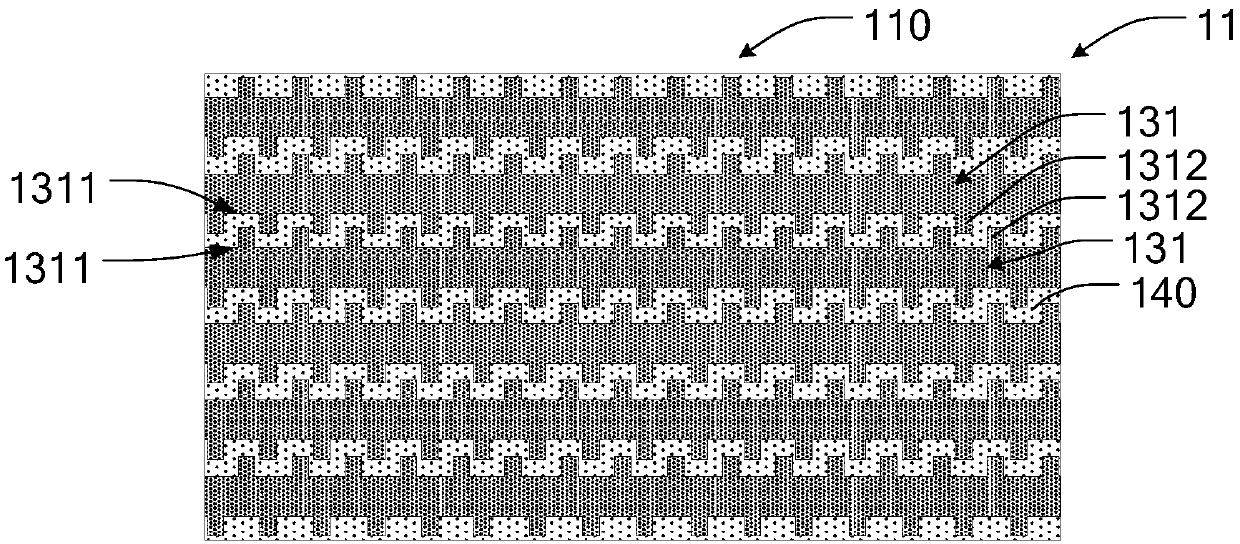
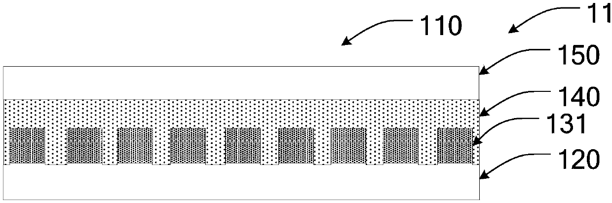
[0032] Such as figure 1 As shown, in this embodiment, the flexible display panel 11 of the present invention has a bending area 101 and a metal layer correspondingly distributed in the bending area 101. The metal layer has several metal traces 131. Generally, , the metal traces 131 are straight traces, and the metal traces 131 are parallel to each other.

[0033] In order to reduce the stress concentration phenomenon of the metal wires 131 in the bending area 101 during bending, and prevent cracks and peeling of the metal wires 131 during bending, resulting in performance degradation, failure, etc., each At least one side of the metal trace 131 has a protrusion 1312 . In this embodiment, both sides of the metal trace 131 are provided with protrusions 1312 , and the protrusions 1312 on both sides of each metal trace 131 are arranged alternately. On the metal trace 131 , the protrusions 1312 on each side are arranged equidistantly. The shape of the protrusion 1312 is at least...

Embodiment 2

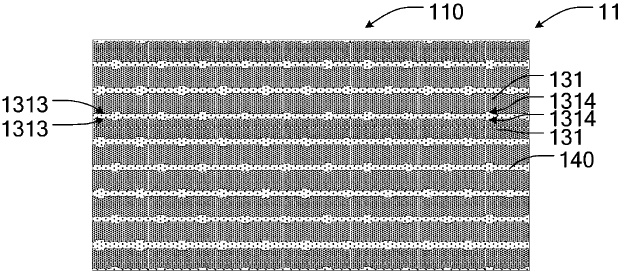
[0038] Such as image 3 As shown, in this embodiment, the flexible display panel 11 of the present invention has a bending area 101 and a metal layer correspondingly distributed in the bending area 101. The metal layer has several metal traces 131. Generally, , the metal traces 131 are straight traces, and the metal traces 131 are parallel to each other.

[0039]In order to reduce the stress concentration phenomenon of the metal wires 131 in the bending area 101 during bending, and prevent cracks and peeling of the metal wires 131 during bending, resulting in performance degradation, failure, etc., each At least one side of the metal trace 131 has a groove 1314 . In this embodiment, both sides of the metal traces 131 are provided with grooves 1314 , and the grooves 1314 on both sides of each metal trace 131 are alternately arranged. On the metal traces 131 , the grooves 1314 on each side are arranged equidistantly.

[0040] In order to optimize the spatial layout of the met...


PUM


Abstract

The invention discloses a flexible display panel and a display device. The flexible display panel comprises a bending region and a metal layer which is correspondingly distributed in the bending region; and the metal layer is provided with a plurality of metal wires, and at least one side edge of each metal wire is provided with a protrusion or a groove. According to the flexible display panel andthe display device, the groove or the protrusion is formed in at least one side of the metal wires, and when the metal wires are bent, the stress concentration phenomenon of the metal wires in the bending region is effectively improved, so that the problems of performance degradation, failure and the like caused by the phenomena such as peeling and the like in bending the metal wires can be solved effectively.

Description

technical field [0001] The invention relates to the fields of display devices and the like, in particular to a flexible display panel and a display device. Background technique [0002] OLED (Organic Light-Emitting Diode) display has become the mainstream display trend due to its self-illumination, wide viewing angle, high contrast, fast response and other characteristics. At present, with people's pursuit of the ultimate display experience, full screens and narrow bezels have become development hotspots in the current display field. However, when an OLED display realizes a full screen and a narrow frame, it is usually necessary to bend the bending area (Pad bending) of the flexible screen, and the metal traces distributed in the bending area will generate stress due to bending. The problem of strain, when the metal wiring has been bent many times or the stress on the metal wiring is too large, there may be breakage, cracks and other undesirable phenomena, which will affect...

Claims


Application Information

Patent Timeline
Patent Type & Authority Applications(China)
IPC IPC(8): H01L27/32
CPCH10K59/10
Inventor 余晶晶
Owner WUHAN CHINA STAR OPTOELECTRONICS SEMICON DISPLAY TECH CO LTD
Why Eureka
Try Eureka