Multi-wire clamp universal live working tool and using method thereof
A technology of live work and tools, applied in the direction of overhead lines/cable equipment, etc., can solve the problems of safety accidents, low efficiency, low automation level, etc., reduce error rate and deviation rate, improve safety factor, and ensure safety Effect
- Summary
- Abstract
- Description
- Claims
- Application Information
AI Technical Summary
Problems solved by technology
Method used
Image
Examples
no. 1 example
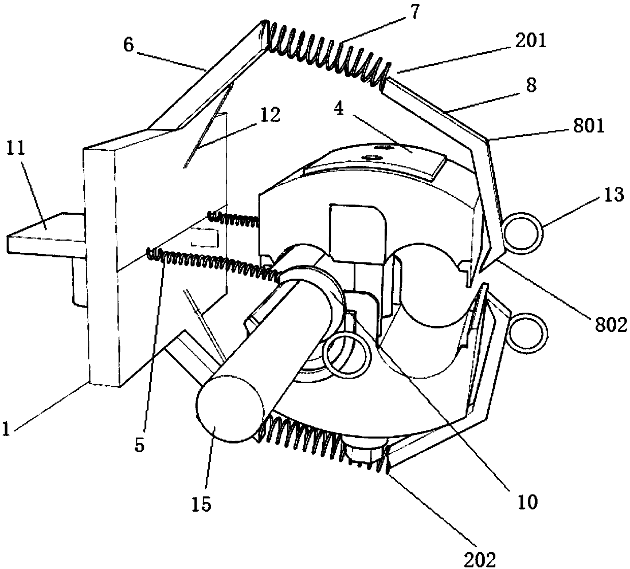
[0033] This embodiment provides a general-purpose live working tool with multiple clamps, such as figure 1 As shown, the installation side plate 1 is included, and the upper hook arm 201 and the lower hook arm 202 are provided on the installation side plate 1, which are opposite up and down and can be stretched. A rod 5 , the wire hook rod 5 is located between the upper hook arm 201 and the lower hook arm 202 .
[0034] The working process or working principle of the common live working tool with multi-clamp is as follows:
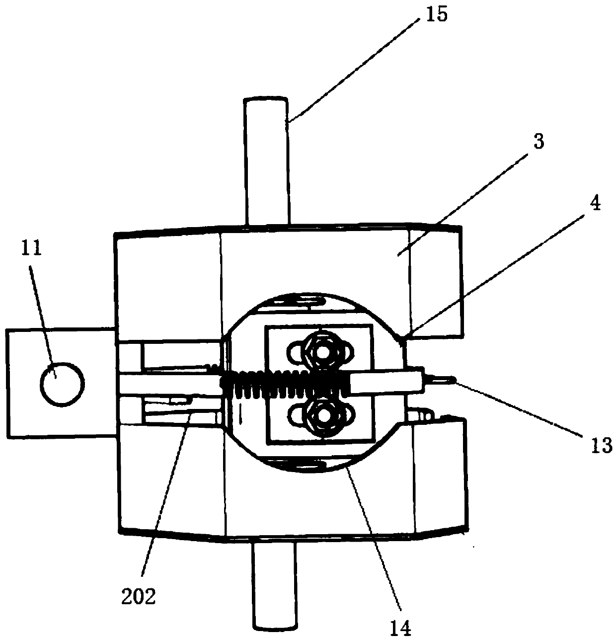
[0035] In the power industry, there are many kinds of wire clips. In order to conveniently illustrate the structure and working principle of the live working tool protected by the present invention, this embodiment takes the puncture wire clip 4 as an example. The structure of the puncture wire clip 4 is as follows: Figure 5 As shown, specifically, the staff turns the puncture wire clip 4 upside down (the nut is downward, such as image 3 shown) into th...
no. 2 example
[0038] This embodiment provides a general-purpose live working tool with multiple clamps, such as figure 1 As shown, the installation side plate 1 is included, and the upper hook arm 201 and the lower hook arm 202 are provided on the installation side plate 1, which are opposite up and down and can be stretched. Rod 5 , the wire hook rod 5 is located between the upper hook arm 201 and the lower hook arm 202 .
[0039] Such as figure 1 and Figure 4 As shown, the upper hook arm 201 and the lower hook arm 202 have the same structure, and are composed of a first rod 6, a first spring 7, and a second rod 8 connected in sequence, and the first rod 6 is far away from One end of the first spring 7 is fixed to the installation side plate 1 and forms an included angle with the surface of the installation side plate 1, and the second rod 8 is provided with at least one bending portion 801 in the middle of the rod 1. A flat hook 802 is provided at the end, and the flat hook 802 of the...
no. 3 example
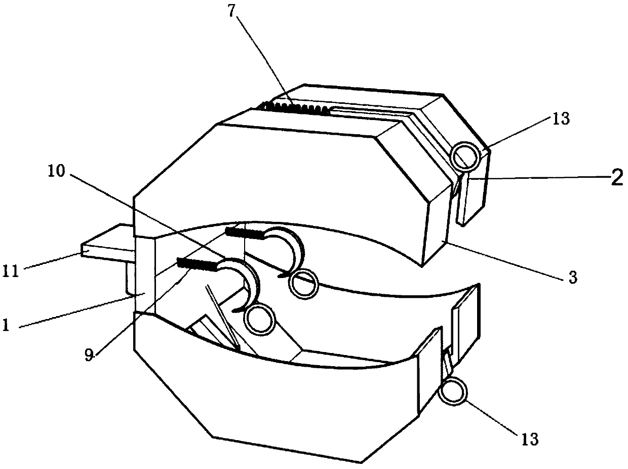
[0043] On the basis of the first embodiment or the second embodiment, as a preference, such as figure 2 As shown, there are two lead wire hook bars 5, which are composed of a second spring 9 and a C-shaped hook 10. One end of the second spring 9 is fixed on the surface of the installation side plate 1, and the other end is connected to C-shaped curved hook 10.
[0044] Because the lead wire 15 in the lead wire port 16 of the puncture wire clamp 4 has a certain length, in order to maintain balance and ensure the stability of the lead wire 15, the C-shaped hook 10 is pulled, and under the elastic force of the second spring 9, the two C-shaped hooks 10 stretches out and catches the lead wire 15 simultaneously, and after the lead wire 15 is fixed, the upper hook arm 201 and the lower hook arm 202 can be pulled to carry out the next operation.
PUM
 Abstract
Description
Claims
Application Information
 - R&D
- Intellectual Property
- Life Sciences
- Materials
- Tech Scout
- Unparalleled Data Quality
- Higher Quality Content
- 60% Fewer Hallucinations
Browse by: Latest US Patents, China's latest patents, Technical Efficacy Thesaurus, Application Domain, Technology Topic, Popular Technical Reports.
© 2025 PatSnap. All rights reserved.Legal|Privacy policy|Modern Slavery Act Transparency Statement|Sitemap|About US| Contact US: help@patsnap.com


