Measurement method of degree of isolation between antennas

A measurement method and antenna spacing technology, which is applied in the direction of measurement devices, measurement of electrical variables, transmission monitoring, etc., can solve the problems of inaccurately obtained isolation, hidden dangers caused by strong self-excitation, and inability to be commercially used on a large scale. Customer satisfaction, enhanced system stability, and improved user experience

Active Publication Date: 2019-04-12
XIAN SAIERCOM CO LTD
View PDF9 Cites 5 Cited by
  • Summary
  • Abstract
  • Description
  • Claims
  • Application Information

AI Technical Summary

Problems solved by technology

In order to prevent self-excitation of the system, the isolation between antennas is usually roughly estimated according to the space loss model during engineering installation, but the external environment, multipath reflection, antenna directivity and other factors make it impossible to accurately obtain the isolation. Bring trouble to construction
Or the system is in weak self-excitation (critical self-excitation), which will lay hidden dangers for strong self-excitation that may occur during long-term network operation in the future during installation and commissioning
One method is to use ICS (adaptive interference cancellation) technology, which can improve the stability of the system, but this method is very expensive and cannot be commercialized on a large scale

Method used


Image

  • Measurement method of degree of isolation between antennas
  • Measurement method of degree of isolation between antennas
  • Measurement method of degree of isolation between antennas

Examples


Embodiment 1

[0037] In order to prevent self-excitation of the system, the isolation between antennas is usually roughly estimated according to the space loss model during engineering installation, but the external environment, multipath reflection, antenna directivity and other factors make it impossible to accurately obtain the isolation. Bring trouble to engineering construction. Or the system is in weak self-excitation (critical self-excitation), which may cause strong self-excitation during installation and commissioning, which may cause strong self-excitation during long-term network operation in the future. One method is to use ICS (adaptive interference cancellation) technology, which can improve the stability of the system, but this method is very expensive and cannot be commercialized on a large scale.

[0038] The method proposed in this embodiment is cheap and easy to implement, and has good accuracy. Without increasing the cost of equipment, it provides a measurement data of ...

Embodiment 2

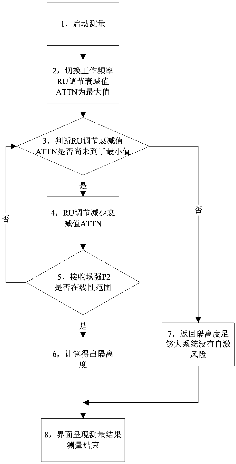
[0046] On the basis of Embodiment 1, this embodiment discloses a specific method for measuring the isolation between antennas.

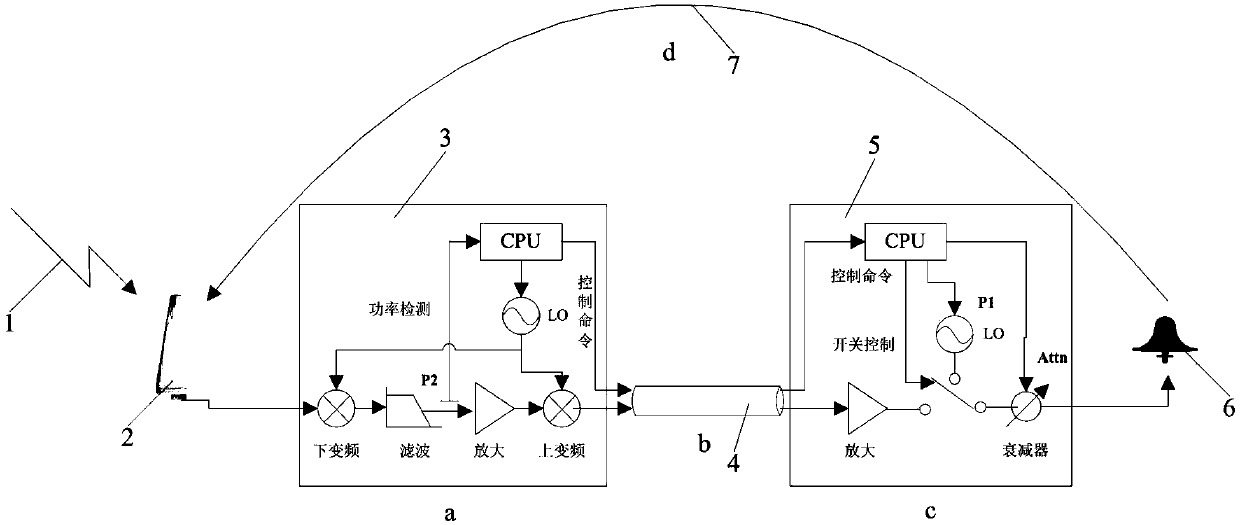
[0047] The wireless coupling indoor coverage system consists of a donor antenna, a first-stage amplification device MU, a radio frequency feeder, a second-stage amplification device RU and a coverage antenna. Ideally, all the RF signals output by the coverage antenna will cover the area to be covered, but in reality, some signals will be fed back to the donor antenna from the space, so a feedback loop is introduced into the system, which is inevitable in actual engineering of.

[0048] The condition that the whole system is not self-excited is that the sum of the gains is less than the sum of the attenuations, and a 15dB margin is left. Therefore, spatial isolation between antennas is required (unit: dB)

[0049] L2 > G1 + G2 - L1 + 15

[0050] Among them: G1 and G2 are the working parameters of the equipment, which can be read directly; L1 is the...


PUM


Abstract

The invention provides a measurement method of a degree of isolation between antennas. The method includes the following steps: step 1, adjusting first-stage amplifying equipment and second-stage amplifying equipment between a donor antenna and a coverage antenna to the same blank working frequency; step 2, adjusting an attenuation value of an attenuator in the second-stage amplifying equipment toobtain an output signal P actually outputted by the second-stage amplifying equipment to the coverage antenna; step 3, detecting a measurement signal P2 of the donor antenna received by the first-stage amplifying equipment; and step 4, calculating the degree of spatial isolation between the donor antenna and the coverage antenna by L2=output signal P-measurement signal P2. The measurement methodof the degree of isolation between the antennas provided by the invention is at a low cost and easy to implement, and has a better accuracy degree. In a case of not increasing equipment costs, knowingof construction personnel on a current system isolation degree is facilitated, and self-excitation is prevented.

Description

technical field [0001] The invention relates to the field of mobile communication, in particular to a method for measuring the isolation between antennas. Background technique [0002] With the deepening popularization of mobile communication services, users have higher requirements on the quality of mobile communication signals. In many scenarios, wireless signals cannot be directly reached due to the obstruction of buildings, so a large number of mobile communication indoor coverage devices are required. The main principle of this device is to use direct coupling or wireless methods to obtain base station signals, and through the first-stage amplification equipment (called MU) and feeder cable transmission, the wireless signals are introduced into places where mobile communication signals are weak, such as basements and tall buildings. Blocking areas, etc., because the loss of the feeder cable is usually relatively large, at this time the system uses the second-stage ampl...

Claims


Application Information

Patent Timeline
Patent Type & Authority Applications(China)
IPC IPC(8): H04B17/10G01R29/00
CPCG01R29/00H04B17/102H04B17/103
Inventor 王德强岳冰曾抓纲
Owner XIAN SAIERCOM CO LTD
Why Eureka
Try Eureka