Linear high-power-factor driving circuit

A high power factor, drive circuit technology, applied in the direction of electric light source, electrical components, electroluminescent light source, etc., can solve the problem that the ripple-free drive circuit is difficult to meet the high power factor requirements, and achieve high PFC and ripple-free Contradictions and conflicts of waves, simple and convenient adjustment, and the effect of improving power factor

Pending Publication Date: 2019-04-12
SUZHOU FEIDAXU MICRO ELECTRONICS CO LTD
View PDF0 Cites 1 Cited by
  • Summary
  • Abstract
  • Description
  • Claims
  • Application Information

AI Technical Summary

Problems solved by technology

The IEC61000-3-2.2000 standard stipulates that in the case of no output ripple, the input PFC (power factor control) ≥ 0.98, THD (Total Harmonic Distortion

Method used


Image

  • Linear high-power-factor driving circuit
  • Linear high-power-factor driving circuit
  • Linear high-power-factor driving circuit

Examples


Embodiment 1

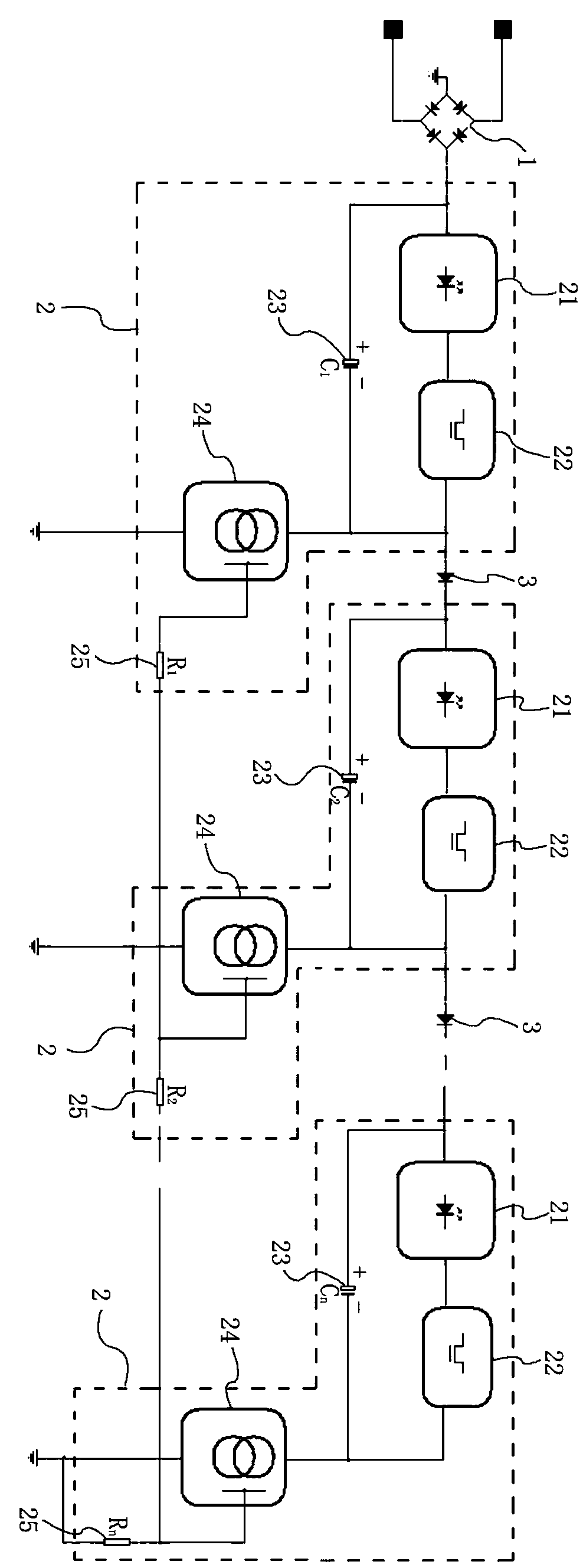
[0040] Reference attached figure 1 to attach image 3 , a linear high power factor drive circuit in this embodiment includes a power supply, a rectifier 1 connected to the power supply at the input end, a plurality of drive circuit units 2 connected in sequence, and the first drive circuit unit 2 ( figure 1 The leftmost driving circuit unit) is connected to the output terminal of the rectifier 1, assuming that there are N driving circuit units 2 in this embodiment, and the distance between the Nth driving circuit unit 2 figure 1 Rectifier 1 in the furthest ( figure 1 The rightmost drive circuit unit in the ).

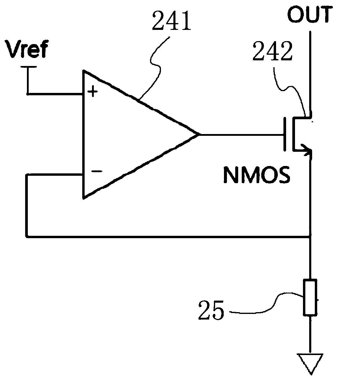
[0041] Such as figure 1 As shown, each of the drive circuit units 2 includes an LED load 21 (one or more LED lamps connected in series), an electronic filter 22, an electrolytic capacitor 23, a current regulator subsection circuit unit 24, and a current detection resistor 25. The LED load 21 and the electronic filter 22 are connected in series to form a first branch...

Embodiment 2

[0058] Reference attached Figure 4 , the difference between the linear high power factor drive circuit in this embodiment and the first embodiment is only that:

[0059] In this embodiment, the floating working mode is adopted. Among the plurality of driving circuit units 2, in each driving single-circuit unit except the last one, the ground terminal of the segment circuit unit 24 of the constant current device and the current detecting resistor 25 at the other end ( figure 1 with Figure 4 The right end as shown) is connected; in the last drive circuit unit 2, the ground terminal of the current regulator section circuit unit 24 is connected to the other end of the current detection resistor 25 and then grounded.

[0060] The isolation segmenter 3 in the present embodiment adopts the NPN triode, and the collector of the triode is connected with the junction of the electronic filter 22 and the segment circuit unit 24 of the constant current device in the previous driving cir...


PUM


Abstract

The invention discloses a linear high-power-factor driving circuit. The linear high-power-factor driving circuit comprises a power supply, a rectifier and a plurality of driving circuit units, whereinthe power supply is connected with the first driving circuit unit through the rectifier; each driving circuit unit comprises an LED load, an electronic filter, an electrolytic capacitor, a galvanostat segmented circuit unit and a current detection resistor; the LED load and the electronic filter are connected in series to form a first branch to be connected with the electrolytic capacitor in parallel; the first branches of the adjacent driving circuit units are connected through an isolation sectionalizer; the output end of the first branch is connected with the input end of the galvanostat segmented circuit unit, and the output end of the galvanostat segmented circuit unit is connected with one end of the corresponding current detection resistor; and the current detection resistors in the adjacent driving circuit units are sequentially connected in series, and the current detection resistor in the last driving circuit unit is grounded. According to the linear high-power-factor driving circuit, the segmented working mode is adopted, so that the working current waveform of the load follows the voltage waveform, thereby improving the power factor.

Description

technical field [0001] The invention relates to a linear high power factor drive circuit, which belongs to the technical field of electronic drive circuit control. Background technique [0002] As an efficient new light source, LED is widely used in lighting in various fields due to its long life, low energy consumption, energy saving and environmental protection. [0003] At present, there is a conflict between high PFC and ripple-free technology in LED drive power supplies. The IEC61000-3-2.2000 standard stipulates that in the case of no output ripple, the input PFC (power factor control) ≥ 0.98, THD (Total Harmonic Distortion) ≤ 10%, while the existing technology It is difficult for a ripple-free drive circuit to meet the high power factor requirements set forth in the standard. Contents of the invention [0004] To solve the above problems, the object of the present invention is to provide a linear high power factor drive circuit. [0005] In order to achieve the ab...

Claims


Application Information

Patent Timeline
IPC IPC(8): H05B33/08H05B44/00
CPCH05B45/00Y02B20/30
Inventor 刘明龙陶冬毅
Owner SUZHOU FEIDAXU MICRO ELECTRONICS CO LTD
Why Eureka
Try Eureka