Ultrasonic capping machine

An ultrasonic and capping machine technology, applied in non-electric welding equipment, welding equipment, metal processing equipment and other directions, can solve the problems of tight pressing and low efficiency of manual loading and unloading.

Inactive Publication Date: 2019-04-16
TIANNENG BATTERY WUHU
View PDF9 Cites 4 Cited by
  • Summary
  • Abstract
  • Description
  • Claims
  • Application Information

AI Technical Summary

Problems solved by technology

[0003] The purpose of the present invention is to provide an ultrasonic capping machine. By setting the lower end of the capping head as a boss shape, the pressing can be made more compact. By setting the feeding conveyor belt, the L-shaped baffle slides o...

Method used


Image

  • Ultrasonic capping machine
  • Ultrasonic capping machine
  • Ultrasonic capping machine

Examples


Embodiment Construction

[0013] In order to deepen the understanding of the present invention, the present invention will be further described below in conjunction with examples, which are only used to explain the present invention and do not constitute a limitation to the protection scope of the present invention.

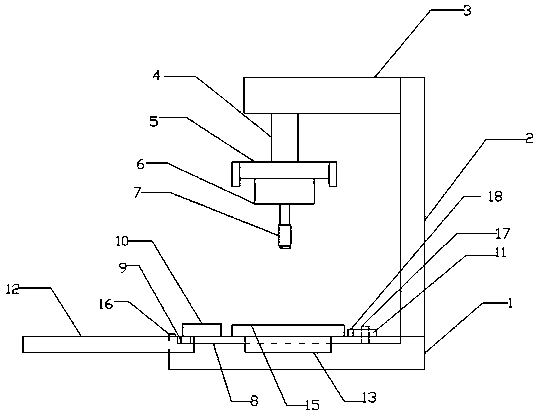
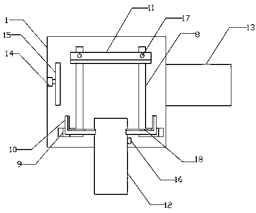
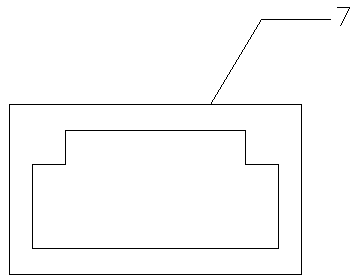
[0014] like Figure 1-3 As shown, this embodiment provides an ultrasonic capping machine, including a workbench 1, the workbench 1 is set as concave, the right end of the workbench 1 is provided with a bracket 2, the left side of the top of the bracket 2 is connected to a beam 3, and the lower end of the beam 3 is provided with a Push down the cylinder 4, the lower end of the push down cylinder 4 is provided with a mounting plate 5, the lower side of the mounting plate 5 is provided with an ultrasonic generator 6, the lower end of the ultrasonic generator 6 is connected with a capping head 7, and the bottom surface of the capping head 7 is set as a boss shape, working The two sides of the...


PUM


Abstract

The invention provides an ultrasonic capping machine. The ultrasonic capping machine comprises a worktable; the worktable is concave; a bracket is arranged at the right end of the worktable; the leftside of the top end of the bracket is connected with a cross beam; a lower pushing cylinder is arranged at the lower end of the cross beam; a mounting plate is arranged at the lower end of the lower pushing cylinder; an ultrasonic generator is arranged on the lower side of the mounting plate; a capping head is connected to the lower end of the ultrasonic generator; the bottom surface of the capping head is boss-shaped; L-shaped slide rails are symmetrically arranged on two opposite sides of the worktable; slide blocks are arranged on the L-shaped slide rails; L-shaped baffle plates are oppositely and symmetrically arranged on the slide blocks on two sides; fixed plates are arranged at the back ends of the L-shaped slide rails; a loading conveying belt is arranged at the front end of the worktable; the back end of the loading conveying belt is embedded in a groove at the front end of the worktable; an unloading conveying belt is arranged on the right side of the worktable; a pushing cylinder is arranged on the left side of the worktable; and a pushing plate is arranged at the front end of the pushing cylinder. As the lower end of the capping head is boss-shaped, the capping is fitter; and the loading conveying belt and the unloading conveying belt are arranged for automatic loading and unloading, so that the working efficiency is improved.

Description

technical field [0001] The invention relates to the field of storage battery production, in particular to an ultrasonic capping machine. Background technique [0002] During the production process of the battery, the battery needs to be capped and welded. The capping head on the lower end of the existing battery ultrasonic capping machine is pressed by a long block. The pressing is not tight, and deviations are likely to occur, and it is all done manually. Loading and unloading, work efficiency is low, so it becomes very important to solve this problem. Contents of the invention [0003] The purpose of the present invention is to provide an ultrasonic capping machine. By setting the lower end of the capping head as a boss shape, the pressing can be made more compact. By setting the feeding conveyor belt, the L-shaped baffle slides on the L-shaped slide rail for feeding. And fixed, by pushing the cylinder to drive the push plate to push the material, and the unloading conv...

Claims


Application Information

Patent Timeline
IPC IPC(8): B23K20/10B23K20/26
CPCB23K20/10B23K20/26
Inventor 钦晓峰陈林陆毅汪俊兵侍子强
Owner TIANNENG BATTERY WUHU
Why Eureka
Try Eureka