Friction welding fixture

A friction welding and fixture technology, applied in the field of friction welding, can solve the problems of inapplicability to batch production, time-consuming and laborious assembly and disassembly, uneven heating, etc., and achieve more uniform heating, fast heating, and high assembly and disassembly efficiency.

Active Publication Date: 2019-04-16
湖南坤鼎数控科技有限公司
View PDF7 Cites 3 Cited by
  • Summary
  • Abstract
  • Description
  • Claims
  • Application Information

AI Technical Summary

Problems solved by technology

For this reason, the patent document CN201721625920.8 discloses a friction stir welding fixture that is convenient for heating the workpiece, so as to realize the fixing of the workpiece to be welded, but each pressing mechanism on it needs to be tightened and disassembled by the operator one by one through tools. The dismantling efficiency is low, the production efficiency is low, and it is not suitable for mass production. At the same time, when the surface of the workpiece to be welded is uneven, each pressing mechanism compresses the workpiece to be welded, which will cause small pressure area and concentrated stress, especially for the workpiece to be welded. When the thin plate structure is easy to deform or even be scrapped, this friction welding fixture is not suitable for friction welding of thin plate workpieces
[0005] In addition, friction stir welding is essentially a metal heated and softened by friction stirring, and superplastic flow occurs, which requires the metal to be fully heated. Now, a heating device is installed on the stirring head, but it cannot solve the fundamental problem.
For this reason, the above-mentioned patent documents realize the heating of the workpieces to be welded by installing electric heating elements at the bottom of the left and right workpieces to be welded, wherein the electric heating elements are embedded in the installation groove, which takes time and effort to assemble and disassemble, and the electric heating elements generally use resistance wires Heating, and this heating method usually has the disadvantages of slow heating, uneven heating, large energy consumption and unsafe electricity consumption

Method used


Image

  • Friction welding fixture
  • Friction welding fixture
  • Friction welding fixture

Examples


Embodiment Construction

[0030] The invention will be further described below in conjunction with the accompanying drawings, but it is not used to limit the scope of the present invention.

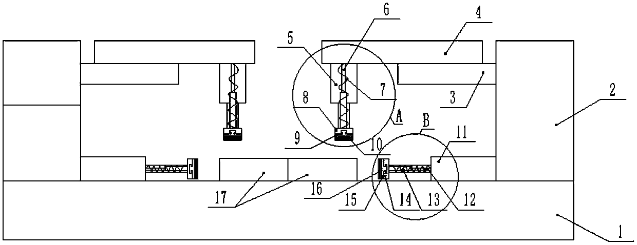
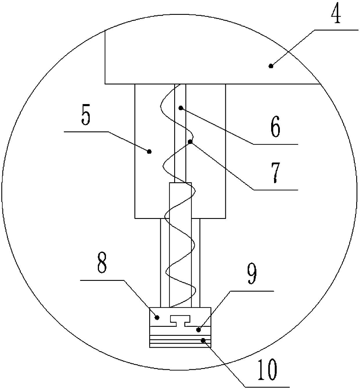
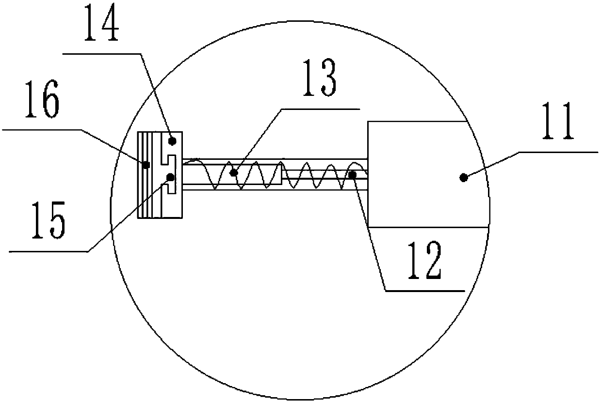
[0031] like Figure 1-6 As shown, a friction welding fixture provided in this embodiment includes a base 1 and two pressing mechanisms symmetrically arranged on both sides above the base 1; the pressing mechanism includes a column 2 for pressing the workpiece 17 to be welded. The top pressing assembly at the top and the side pressing assembly for pressing the sides of the workpiece 17 to be welded; the column 2 is installed above the base 1, specifically, the column 2 is provided with a plurality of bolt holes, and the base 1 There are threaded holes corresponding to the positions of the bolt holes of the column 2, so that the column 2 and the base 1 are tightly connected by bolts, and the detachable connection between the base 1 and the column 2 is realized, and the assembly and disassembly are simple and conveni...


PUM


Abstract

The invention discloses a friction welding fixture, which includes a base and two compressing mechanism arranged symmetrically on both sides of the upper part of the base. The compressing mechanism includes a vertical column, a top compressing assembly for compressing the top of a workpiece and a side face compressing assembly for compressing the side face of the workpiece; the vertical column isinstalled on the upper part of the base, and the top compressing assembly includes a motor, a guide rail, a screw rod, a sliding block, a first lifting part, a top fixing plate, a top moving block, atop flexible pressing plate, a second lifting part and a first spring; the motor is installed in the vertical column, the guide rail is installed horizontally on the upper part of the inner side faceof the vertical column, the screw rod is rotatably connected with the motor, the sliding block is slidably installed on the guide rail, the bottom of the sliding block is connected with a nut, the nutexternally sleeve the screw rod, and the bottom of the inner end of the sliding block is connected with the upper part of the first lifting part; and the lower part of the first lifting part is connected with the top fixing plate, and the sliding block is connected with the top fixing plate through the second lifting part. According to the friction welding fixture, to-be-welded workpieces are conveniently fixed, and the friction welding fixture can be applied to mass production and friction welding of thin plate type workpieces.

Description

technical field [0001] The invention relates to the technical field of friction welding, in particular to a friction welding fixture. Background technique [0002] Friction welding is a method of using the heat generated by the mutual movement and friction of the workpiece ends to make the ends reach a thermoplastic state, and then quickly upset to complete the welding. Friction welding can easily join the same or dissimilar materials, including metals, some metal matrix composites, ceramics and plastics. [0003] Friction stir welding uses a non-consumable stirring head with a special shape, which is inserted into the workpiece to be welded by rotation, and then moves forward along the surface of the workpiece to be welded. The material is heated to a thermoplastic state. Driven by the high-speed rotation of the stirring head, the material in the plastic state is transferred from front to back around the stirring head. At the same time, combined with the extrusion effect o...

Claims


Application Information

Patent Timeline
Patent Type & Authority Applications(China)
IPC IPC(8): B23K20/12B23K20/26
CPCB23K20/12B23K20/26
Inventor 雷勋发宋勇
Owner 湖南坤鼎数控科技有限公司
Why Eureka
Try Eureka