Perforating device and perforating method for cambered surface building outer wall lamp installation

A lamp installation and drilling device technology, applied in the direction of manufacturing tools, stone processing tools, stone processing equipment, etc., can solve the problems of drill bit deviation, lamp hole deviation, uneven force, etc., to ensure rotation flexibility and pumping Stretching flexibility, avoiding uneven force deviation, ensuring the effect of punching volume

Active Publication Date: 2019-04-16
重庆集凯科技服务有限公司
View PDF8 Cites 0 Cited by
  • Summary
  • Abstract
  • Description
  • Claims
  • Application Information

AI Technical Summary

Problems solved by technology

[0002] Nowadays, in order to meet the needs of decoration and lighting, most buildings drill holes on the outer wall to install lamps. Most of the existing drilling devices slide the motor on the guide rail, and the bottom of the guide rail is provided with flat fixing feet. However, on the outer wall of the curved building, the end When the flat fixing feet are attached to the outer wall, they will only be supported by a single line. During the drilling process, they will shake, causing the lamp hole to be deviated. Cutting contact, it is very easy to cause the drill bit to deviate or break due to uneven force

Method used


Image

  • Perforating device and perforating method for cambered surface building outer wall lamp installation
  • Perforating device and perforating method for cambered surface building outer wall lamp installation
  • Perforating device and perforating method for cambered surface building outer wall lamp installation

Examples


Embodiment Construction

[0024] The following will clearly and completely describe the technical solutions in the embodiments of the present invention with reference to the accompanying drawings in the embodiments of the present invention. Obviously, the described embodiments are only some, not all, embodiments of the present invention. Based on the embodiments of the present invention, all other embodiments obtained by persons of ordinary skill in the art without making creative efforts belong to the protection scope of the present invention.

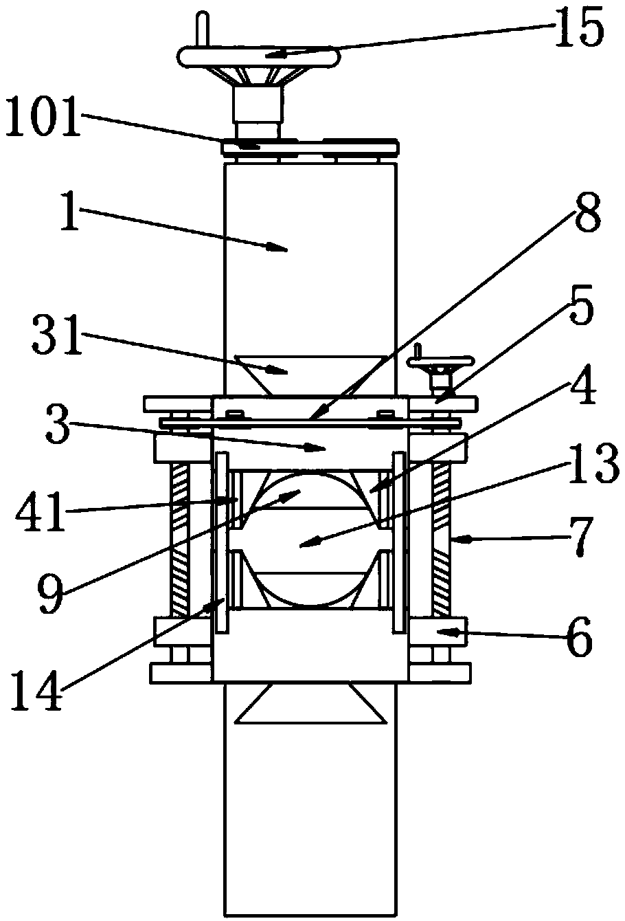
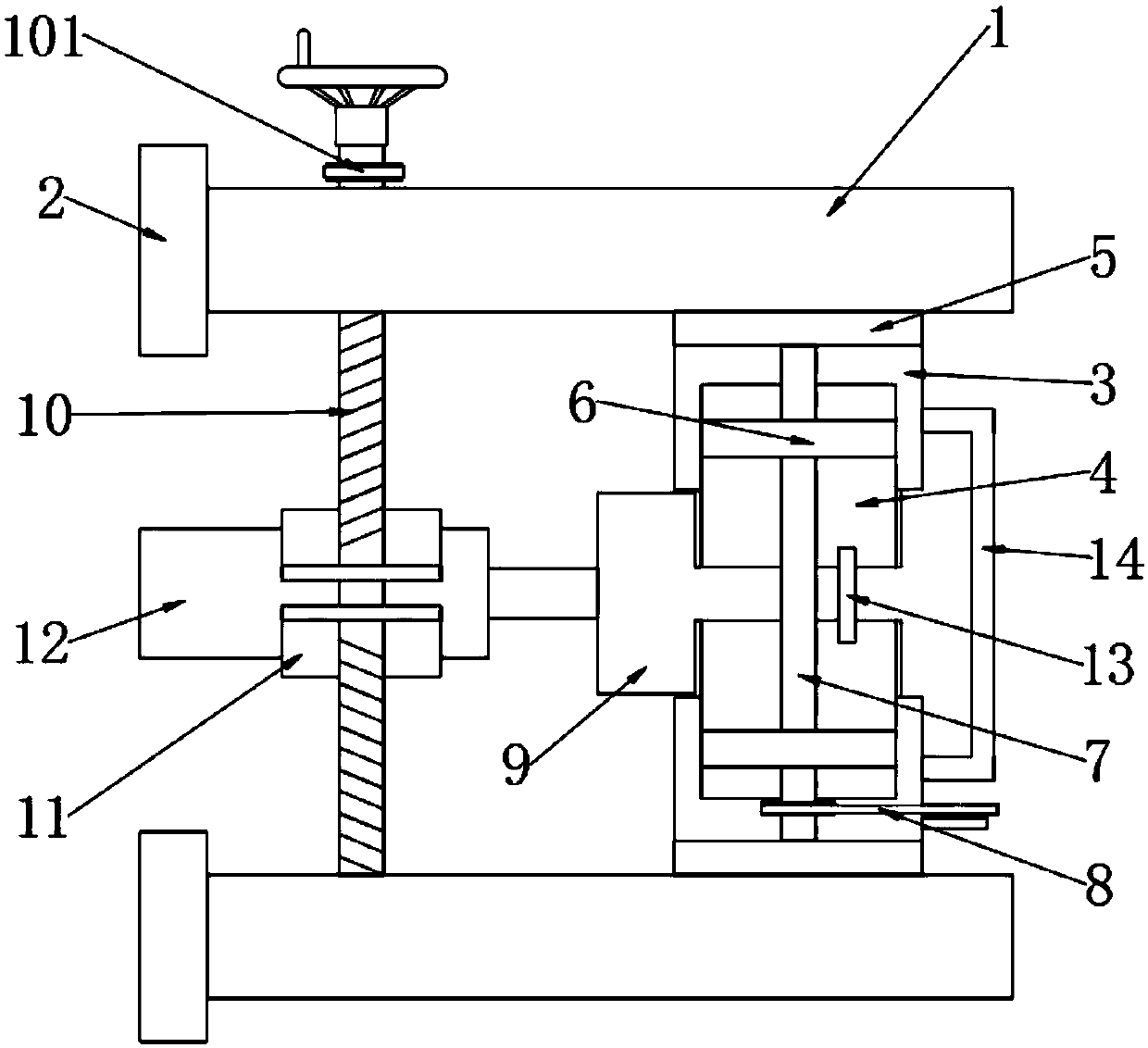
[0025] see Figure 1-3 , the present invention provides a technical solution: a punching device for installing lamps on the outer wall of a curved building, including two sets of upper and lower rectangular fixing columns 1, the rear ends of the fixing columns 1 are provided with V-shaped fixing feet 2, two sets of The opposite end surface of the fixed column 1 is slidingly provided with a U-shaped moving block 3, and the opposite end surfaces of two groups of...


PUM


Abstract

The invention discloses a perforating device for cambered surface building outer wall lamp installation in the technical field of perforating devices. The perforating device for cambered surface building outer wall lamp installation comprises two upper and lower groups of rectangular fixed pillars, wherein V-shaped fixed feet are arranged at the back ends of the fixed pillars; U-shaped moving blocks are slidably arranged on the opposite end surfaces of the two groups of fixed pillars; a perforating motor is arranged between two groups of movable V-shaped clamping blocks; two left and right groups of bi-directional screw rods are vertically inserted between the positions, close to the back ends, of the two groups of fixed pillars; two groups of matched semi-circular clamping covers are inserted into the middle parts of the two groups of bi-directional screw rods in a screw-thread fit way; a perforating drill bit is arranged between the two groups of semi-circular clamping covers; and two left and right groups of push-and-pull handles are arranged between the front ends of the two groups of U-shaped moving blocks. The device is suitable to be fixed onto a house type outer wall through the V-shaped fixed feet without shaking, so that the stability in perforating is ensured; and by adopting the movable V-shaped clamping blocks and the semi-circular clamping covers rotating synchronously, the central axes of the perforating motor and the perforating drill bit are always consistent to the circle center of a lamp hole without deviating.

Description

technical field [0001] The invention relates to the technical field of punching devices, in particular to a punching device and a punching method for installing lamps on the outer wall of a curved building. Background technique [0002] Nowadays, in order to meet the needs of decoration and lighting, most buildings drill holes on the outer wall to install lamps. Most of the existing drilling devices slide the motor on the guide rail, and the bottom of the guide rail is provided with flat fixing feet. When the flat fixing feet are attached to the outer wall, they will only be supported by a single line. During the drilling process, they will shake, causing the lamp hole to be deflected, and when the drilling bit just touches the outer wall of the arc surface to punch holes, the end of the drill bit will be in contact with the outer wall. Cutting contact, it is very easy to cause the drill bit to deviate or break due to uneven force. Therefore, we propose a punching device an...

Claims


Application Information

Patent Timeline
IPC IPC(8): B28D1/14
CPCB28D1/14
Inventor 朱雪玉
Owner 重庆集凯科技服务有限公司
Why Eureka
Try Eureka