Screen laminating device and laminating method

A technology for bonding devices and screens, which is applied to household components, household appliances, and other household appliances. It can solve problems such as defective products, relative contact movement between flexible films and curved surface protection covers, and unoptimized user experience. The effect of reducing defective products and avoiding air bubbles and wrinkles

Pending Publication Date: 2019-04-16
汪恒坤
View PDF0 Cites 13 Cited by
  • Summary
  • Abstract
  • Description
  • Claims
  • Application Information

AI Technical Summary

Problems solved by technology

[0002] Capacitive touch screens and other types of touch screens have been widely used in people's lives, but as far as general touch screen products are concerned, the screens are generally plate-shaped. Although this touch screen can realize touch control And the effect of displaying images, but its use experience is often not optimal, so with the development of touch display technology, some curved touch screens have appeared.
[0003] For the existing production equipment of curved display screens, it is generally designed for curved display screens with an obtuse angle structure greater than 90 degrees. For the lamination between the protective covers, the flexible film is easy to contact with the curved edge of the curved protective cover, and it is easy to cause relative contact movement between the flexible film and the curved protective cover during the lamination process, resulting in defective products

Method used


Image

  • Screen laminating device and laminating method
  • Screen laminating device and laminating method
  • Screen laminating device and laminating method

Examples


Embodiment 1

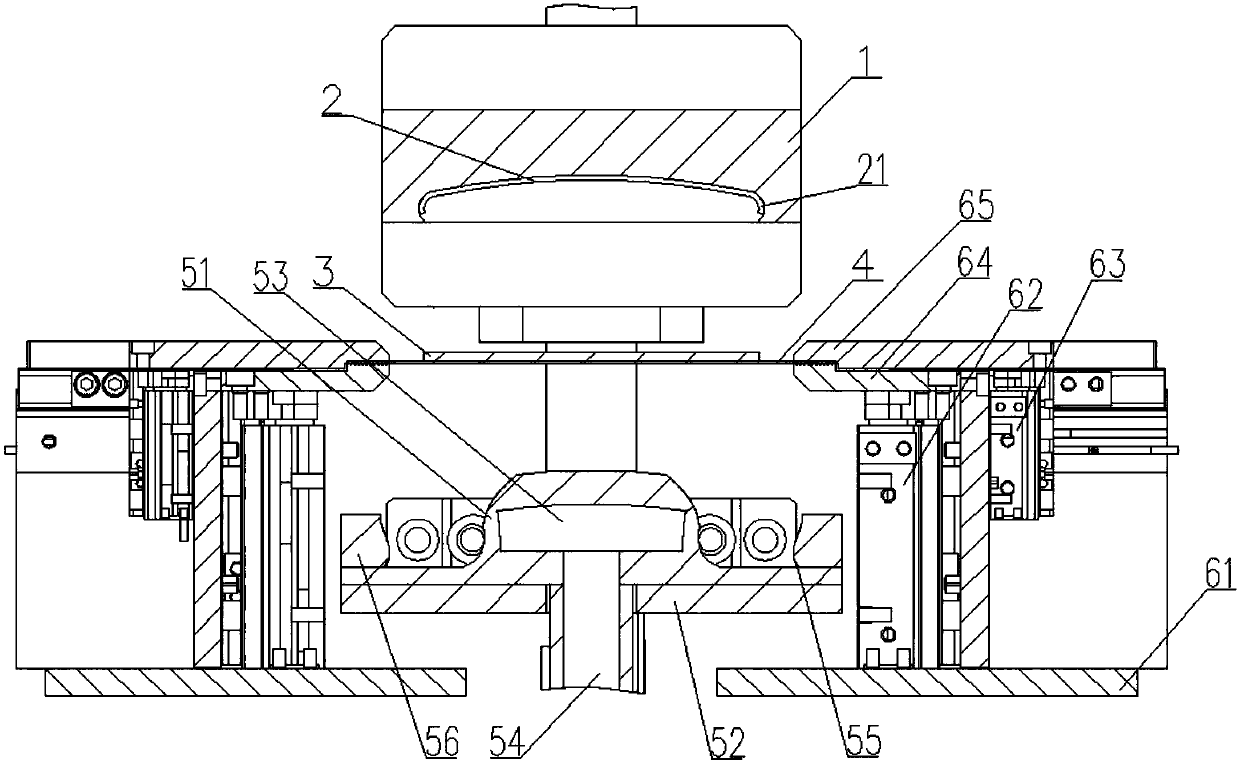
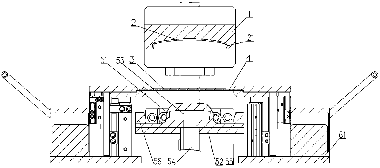
[0039] like Figure 1 to Figure 8 shown, Figure 1 to Figure 8 The bonding and non-fitting in are the bonding and non-fitting between the curved protective cover sheet and the flexible film. The screen fitting device of the present invention includes an upper cavity and a lower cavity, the upper cavity and the lower cavity are arranged in cooperation, and the upper cavity and the lower cavity can move up and down; When the upper cavity and the lower cavity are closed, a closed space is formed in the upper cavity and the lower cavity; the upper cavity is provided with a placing platform 1 and a curved protective cover plate 2, and the lower cavity A flexible film 3, a carrier tape 4, and a lifting and pressing part 5 are provided; the placing platform 1 is used to place the curved protective cover 2, and the flexible film 3 is placed on the carrier tape 4. The carrier tape 4 is placed on the lifting and pressing part 5, and the flexible film 3 and the curved protective cover ...

Embodiment 2

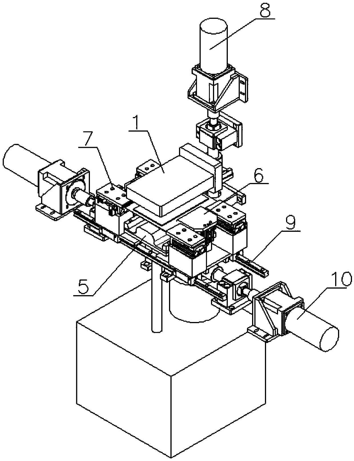
[0047] The placing platform 1 is used to support the curved protective cover plate 2, and the placing platform 1 is generally rectangular and has a certain thickness; the placing platform 1 is connected with the lifting device 8 inside the closed space, The lifting device 8 can move the placing platform 1 downward in the direction of the lifting and pressing part 5 . The upper part of the lifting and pressing part 5 is provided with the pressing block 51 ; the height of the pressing block 51 can be adjusted through the lifting and pressing part 5 .

[0048] The lower end surface of the placing platform 1 is provided with an installation groove for accommodating the curved protective cover plate 2, so that the supporting curved protective cover plate 2 can be fixed; The vacuum holes on the surface of the curved protective cover plate 2 are used for adsorbing and supporting the curved protective cover plate 2 .

[0049] The gripping device 6 is arranged on both sides of the lif...

Embodiment 3

[0066] like Figure 1 to Figure 4 As shown, the pressing device 7 is arranged on the side of the gripping device 6, and the pressing device 7 is symmetrically arranged on the base 61 on both sides of the pressing block 51; preferably, The number of the pressing devices 7 is set to four, and the same base 61 is provided with two pressing devices 7 corresponding to the same gripping device 6 . The center line between the two sides is symmetrically arranged on both sides of the gripping device 6 , and the pressing device 7 can move horizontally with the base 61 .

[0067] The pressing device 7 includes a third cylinder 71 , a mounting seat 72 and a pressing block 73 , the pressing block 73 is fixed on the telescopic rod of the third cylinder 71 through the mounting seat 72 , and the third The telescopic rod of the cylinder 71 can drive the pressing block 73 to move in the horizontal direction through the mounting seat 72 . The pressing block 73 is set as a plate-like structure ...


PUM


Abstract

The invention discloses a screen laminating device and a laminating method. The screen laminating device comprises an upper cavity body and a lower cavity body, wherein the upper cavity body and the lower cavity body are arranged in a matched mode, and the upper cavity body and the lower cavity body can move up and down; the upper cavity body is provided with a placement platform and a curved surface protection cover plate, and the lower cavity body is provided with a flexible film, a carrying belt and a lifting and pressurizing part; and the placement platform is used for placing the curved surface protection cover plate, the flexible film is placed on the carrying belt, the carrying belt is made of a flexible material, the carrying belt is placed on the lifting and pressurizing part, andthe flexible film and the curved surface protection cover plate are correspondingly arranged up and down. According to the screen laminating device and the laminating method, the flexible film is attached to the curved surface protection cover plate through adjusting the height positions of the placement platform and the lifting and pressurizing part; and for attaching the flexible film to the curved surface protection cover plate with right angle or acute angle edges, under the action of the expansion deformation of a pressing block and a pressing device, earlier contact between the end partof the flexible film and the curved surface edge position of the curved surface protection cover plate is avoided, and produced defective products are reduced.

Description

technical field [0001] The invention relates to the technical field of screen fabrication, in particular to a screen laminating device and a laminating method. Background technique [0002] Capacitive touch screens and other types of touch screens have been widely used in people's lives, but as far as general touch screen products are concerned, the screen as a whole is in a plate-like structure. Although this kind of touch screen can realize touch control As well as the effect of displaying images, the user experience is often not optimal. Therefore, with the development of touch display technology, some curved touch screens have appeared. [0003] For the production equipment of the existing curved display screen, it is generally designed for the curved display screen with an obtuse angle structure greater than 90 degrees. When the curved edge of the display screen is set to a right angle or an acute angle structure smaller than the right angle, it is suitable for flexible...

Claims


Application Information

Patent Timeline
IPC IPC(8): B29C63/02B29L31/34
CPCB29C63/02B29C63/0004B29L2031/3475
Inventor 汪恒坤
Owner 汪恒坤
Why Eureka
Try Eureka