Anti-rolling lifeboat and anti-rolling method

A technology for lifeboats and hulls, which is applied in the directions of ship safety, ships, transportation and packaging, can solve problems such as lifeboats overturning, and achieve the effect of being difficult to overturn and toppling.

Inactive Publication Date: 2020-04-10
ZHEJIANG INT MARITIME COLLEGE
View PDF5 Cites 0 Cited by
  • Summary
  • Abstract
  • Description
  • Claims
  • Application Information

AI Technical Summary

Problems solved by technology

The lifeboat floats on the water, and there is a risk of tipping the lifeboat when the water waves hit the side of the lifeboat

Method used


Image

  • Anti-rolling lifeboat and anti-rolling method
  • Anti-rolling lifeboat and anti-rolling method
  • Anti-rolling lifeboat and anti-rolling method

Examples


Embodiment 1

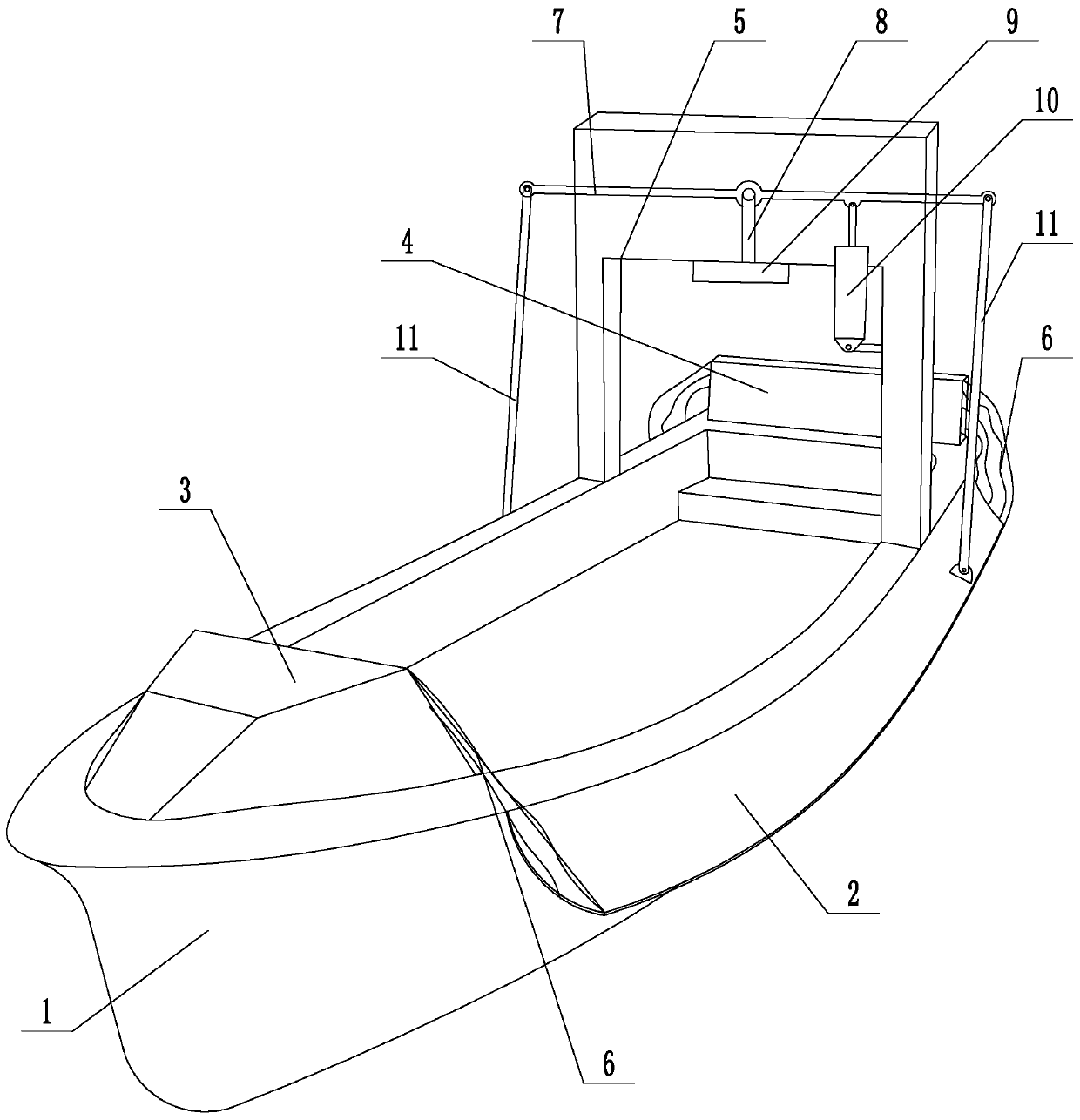
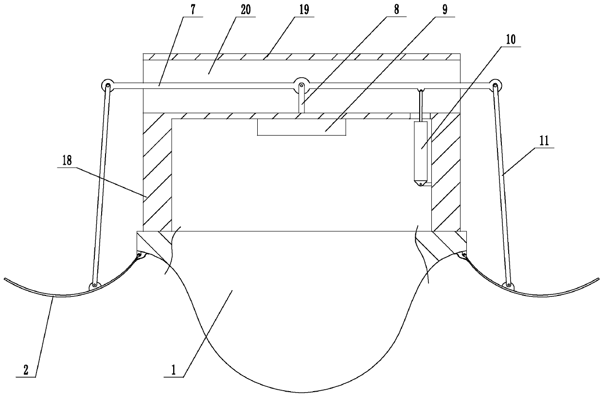
[0021] Embodiment 1: a kind of anti-rolling lifeboat (see attached figure 1 , attached figure 2 ), including the hull 1, two water-retaining flaps 2 respectively arranged on the left and right sides of the hull, the front end of the hull is provided with an upwardly protruding front cover 3, the rear end of the hull is provided with a tailgate 4, and the position near the rear end of the hull is Connect the installation frame 5, the edge of the water retaining flap is hinged on the upper edge position of the hull, and the water retaining cloth 6 is connected between the front end of the water retaining flap and the front cover and between the rear end of the water retaining flap and the tailgate. Drive rod 7, support rod 8, inclination sensor 9, and drive electric cylinder 10 are installed on the mounting frame, the middle of the drive rod is hinged on the support rod, the left and right ends of the drive rod are hinged with connecting rods 11, and the lower ends of the two c...

Embodiment 2

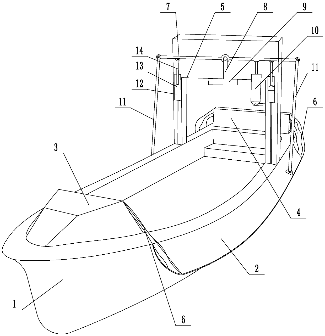
[0024] Embodiment 2: a kind of anti-rolling lifeboat (see attached image 3 , attached Figure 4 ), its structure is similar to that of Embodiment 1, the main difference is that in this embodiment, the left and right sides of the mounting frame are provided with a piston chamber 12, a piston 13 is installed in the piston chamber, the upper end of the piston is hinged to the piston rod 14, and the upper ends of the two piston rods are respectively hinged Near the left and right ends on the driving rod, some inflatable concave cavities 15 are arranged on the left and right side walls of the hull, and air bag bags 16 are installed in the inflatable concave cavities, and the air bag bag on the left side outer wall of the hull passes through The pipeline is connected, and the air bag on the outer wall on the right side of the hull communicates with the lower end of the piston cavity on the right side through the pipeline. Other structures are the same as in Embodiment 1.

[0025]...


PUM


Abstract

The invention discloses an anti-roll lifeboat and an anti-roll method, and aims at solving the defects that the lifeboat has the risk of rolling when the lifeboat is placed on a water surface, and thelifeboat has the risk of tipping when water waves are flapped on the side wall of the lifeboat. The lifeboat comprises a ship body and two water retaining turning plates respectively arranged on theleft side and right side of the ship body, wherein the front end of the ship body is provided with a front ship cover, the rear end of the ship body is provided with a rear baffle plate, the ship bodyis connected with a mounting frame, the upper edge of the water retaining turning plate is hinged at the upper edge position of the ship body, water retaining cloth is connected between the front endof the water retaining turning plates and the front ship cover and between the rear end of the water retaining turnover plates and the rear baffle plate; a driving rod, a supporting rod, an inclination angle sensor and a driving electric cylinder are arranged on a mounting frame; the middle of the driving rod is hinged on the supporting rod; the left end and right end of the driving rod are hinged with connecting rods; the lower ends of the two connecting rods are respectively hinged on the two water retaining turning plates, a telescopic rod of the driving electric cylinder is hinged on thedriving rod for driving the driving rod to rotate, and the inclination angle sensor and the driving electric cylinder are both electrically connected with the same controller.

Description

technical field [0001] The invention relates to a ship, more specifically, it relates to an anti-rolling lifeboat and an anti-rolling method. Background technique [0002] At present, most large ships are equipped with lifeboats, which can be used to escape or avoid danger when encountering a dangerous situation. The lifeboat is generally embedded on the large hull. When the lifeboat needs to be used, the lifeboat is hoisted and lowered to the water surface by a crane. In many cases, the process of lowering the lifeboat is not in the vertical lowering state, and the lifeboat is in a certain inclined state when it touches the water surface. At this time, the lifeboat has the risk of tipping over. The lifeboat floats on the water, and there is a risk of tipping the lifeboat when water waves hit the side walls of the lifeboat. Contents of the invention [0003] The invention overcomes the disadvantages of the risk of tipping over when the lifeboat is lowered to the water su...

Claims


Application Information

Patent Timeline
Patent Type & Authority Patents(China)
IPC IPC(8): B63B43/04
CPCB63B43/04
Inventor 马瑶珠赵陈陈正寿
Owner ZHEJIANG INT MARITIME COLLEGE
Why Eureka
Try Eureka