Grain and oil purification and extraction device

An extraction device, a technology for grain and oil, applied in the direction of fat oil/fat refining, fat production, etc., can solve the problems of inconvenient sesame oil skimming, low efficiency, and large shaking range of sesame oil, and achieve a simple structure, meet market demand, and increase efficiency. Effect

Pending Publication Date: 2019-04-16
BOHAI UNIV
View PDF0 Cites 2 Cited by
  • Summary
  • Abstract
  • Description
  • Claims
  • Application Information

AI Technical Summary

Problems solved by technology

[0002] Shaking sesame oil is an important part of the production process of small grinding sesame oil. The quality of sesame oil shaking equipment directly affects the oil yield of sesame slurry and the efficiency of sesame oil separation. Although artificial shaking sesame oil can shake sesame oil in all directions, it is inefficient and time-consuming. At the same time, the existing sesame oil shaking machine can only shake the oil pan in one direction, so that the sesame oil gathers at both ends of the oil pan in the shaking direction, and the slurry perpendicular to the shaking direction cannot be shaken, and the sesame oil inside cannot be separated out. Continuously rotate the oil pan manually to realize the shaking of the oil pan in multiple directions. At the same time, at different stages of shaking the sesame oil, the shaking amplitude of the oil pan cannot be adjusted. The shaking range of the initial shaking of the sesame oil is too small, which seriously affects the efficiency of shaking the oil. The shaking range is too large, so that the slurry and sesame oil are remixed, which is not convenient for the sesame oil to be skimmed out, and cannot meet the actual needs, so we invented a grain and oil purification and extraction device

Method used


Image

  • Grain and oil purification and extraction device
  • Grain and oil purification and extraction device
  • Grain and oil purification and extraction device

Examples


Embodiment Construction

[0014] In order to make the purpose, technical solutions and advantages of the embodiments of the present invention clearer, the technical solutions in the embodiments of the present invention will be clearly and completely described below in conjunction with the drawings in the embodiments of the present invention. Obviously, the described embodiments It is a part of embodiments of the present invention, but not all embodiments. Based on the embodiments of the present invention, all other embodiments obtained by persons of ordinary skill in the art without creative efforts fall within the protection scope of the present invention.

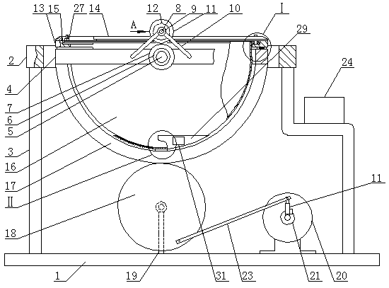
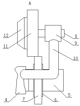
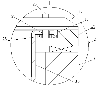
[0015] A grain and oil purification and extraction device, as shown in the figure, includes a base 1, a fixed ring 2 is arranged above the base 1, the fixed ring 2 and the base 1 are fixedly connected by a bracket 3, a movable ring 4 is arranged in the fixed ring 2, and the movable ring 4 The middle of the front side and the rear side are respecti...


PUM


Abstract

The invention relates to a grain and oil purification and extraction device. The device comprises s base, a fixed ring is arranged on the upper portion of the base, the fixed ring is fixedly connectedwith the base through a support, a movable ring is arranged in the fixed ring, the middles of the front side and the rear side of the movable ring are connected with the inner ends of cross shafts through bearings respectively, the outer ends of the cross shafts are fixedly connected with the fixed ring separately, a damping bearing is fixedly installed on the periphery of the cross shaft on thefront side, an annular gear is fixedly installed on the periphery of the damping bearing, a short shaft is arranged over the cross shafts, a shaft base is installed at the front end of the periphery of the short shaft through a bearing, the shaft base is fixedly connected with the movable ring through a support rod, a gear is fixedly installed at the rear end of the short shaft, and the gear is inmeshing cooperation with the annular gear. Accordingly, the structure is simple, a swinging oil pot can rotate continuously, shaking of the oil pot in all directions is achieved, the sesame oil shaking efficiency is improved, the sesame oil in paste is separated out more thoroughly, and meanwhile the oil pot shaking amplitude can be controlled; requirements of sesame oil shaking in different stages are met, the market requirements can be met, and the device is suitable for popularization.

Description

technical field [0001] The invention belongs to the field of processing equipment, in particular to a grain and oil purification and extraction device. Background technique [0002] Shaking sesame oil is an important part of the production process of small grinding sesame oil. The quality of sesame oil shaking equipment directly affects the oil yield of sesame slurry and the efficiency of sesame oil separation. Although artificial shaking sesame oil can shake sesame oil in all directions, it is inefficient and time-consuming. At the same time, the existing sesame oil shaking machine can only shake the oil pan in one direction, so that the sesame oil gathers at both ends of the oil pan in the shaking direction, and the slurry perpendicular to the shaking direction cannot be shaken, and the sesame oil inside cannot be separated out. Continuously rotate the oil pan manually to realize the shaking of the oil pan in multiple directions. At the same time, at different stages of sh...

Claims


Application Information

Patent Timeline
Patent Type & Authority Applications(China)
IPC IPC(8): C11B3/00
CPCC11B3/00
Inventor 张明张德福李媛方亚琴吴元庆刘春梅吕航杨喜宝
Owner BOHAI UNIV
Why Eureka
Try Eureka