Supercharge Your Innovation With Domain-Expert AI Agents!

Construction method for cable bridge bracket installation rail in utility tunnel

A technology for integrated pipe gallery and cable bridge, which is applied in the direction of cable laying equipment, artificial islands, water conservancy projects, etc. It can solve the problems affecting the stable support of the cable bridge by the bracket, and achieve the effect of stable and reliable support

Inactive Publication Date: 2019-04-16
CHINA MCC5 GROUP CORP
View PDF2 Cites 1 Cited by
  • Summary
  • Abstract
  • Description
  • Claims
  • Application Information

AI Technical Summary

Problems solved by technology

[0002] The installation track of the cable tray bracket in the comprehensive pipe gallery is mainly used for the fixed installation of each bracket. The installation height of each bracket can be adjusted vertically along the T-shaped groove of the installation track. For the track, it is necessary to ensure that the upper surface of each bracket at the same support height is in the same horizontal plane, so as to ensure that each bracket forms a stable and reliable support for the entire cable tray. Therefore, it is necessary to ensure that the installation track is vertical and its outer surface is in line with the comprehensive The surface of the inner side wall of the pipe gallery is flush. In the current construction method, the installation track is directly connected with the steel mesh, and then the pouring operation is performed, which often causes the installation track to be inclined laterally (that is, the upper end is left, the lower end is right, or the upper end is inclined). right, lower end to the left), inclination in the internal and external directions (that is, convex and concave or concave and convex), which affects the stable support of the bracket to the cable tray

Method used


Image

  • Construction method for cable bridge bracket installation rail in utility tunnel
  • Construction method for cable bridge bracket installation rail in utility tunnel
  • Construction method for cable bridge bracket installation rail in utility tunnel

Examples


Embodiment Construction

[0023] The present invention will be further described below in conjunction with the accompanying drawings.

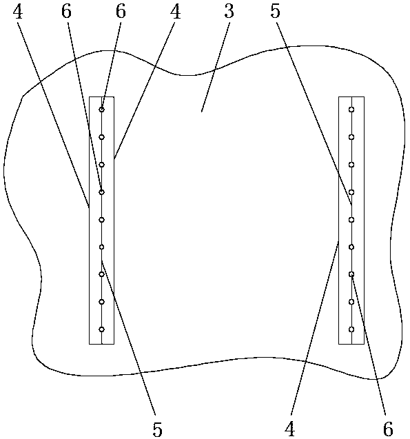
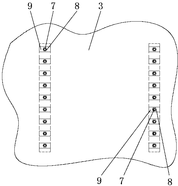
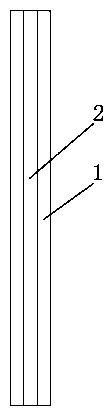
[0024] Such as Figures 1 to 6 As shown, the construction method of the installation track of the cable bridge bracket in the comprehensive pipe gallery, the installation track 1 has a T-shaped groove 2 opened along its length direction, and before installing the pouring formwork 3 of the internal side wall of the comprehensive pipe gallery, the pouring formwork 3 Measure and set out the line, measure and release the outline 4 of the installation track 1, and it is in a vertical state, and then detachably fix the installation track 1 in the area of ​​the outline 4 and match it, and install the T-shaped slot 2 of the track 1 Closely attached to the inner surface of the pouring formwork 3, after the fixed connection between the installation track 1 and the pouring formwork 3 is completed, the openings at the upper and lower ends of the installation track 1 are blocked wi...


PUM


Abstract

The invention relates to the technical field of utility tunnel construction, and discloses a construction method for a cable bridge bracket installation rail in a utility tunnel. A T-shaped groove isformed in the installation rail in the length direction of the installation rail, before a pouring formwork of a side wall in the utility tunnel is installed, surveying and setting out are conducted on the pouring formwork first, the contour line of the installation rail is surveyed, and the contour line is in a vertical state; afterwards, the pouring formwork is installed, pouring operation can be conducted in the pouring formwork, and after concrete is solidified, connection between the installation rail and the pouring formwork can be removed. By means of the construction method, it can beeffectively ensured that the installation rail is vertical, the outer surface of the installation rail is flush with the surface of the side wall in the utility tunnel, the situation that the installation rail is tilted transversely or inwards or outwards can be avoided, it is ensured that the upper surfaces of various brackets are in the same horizontal plane, and it is ensured that all the brackets provide stable and reliable supporting for a whole cable bridge.

Description

technical field [0001] The invention relates to the technical field of construction of a comprehensive pipe gallery, in particular to a construction method for installing a track of a cable bridge bracket in a comprehensive pipe gallery. Background technique [0002] The installation track of the cable tray bracket in the comprehensive pipe gallery is mainly used for the fixed installation of each bracket. The installation height of each bracket can be adjusted vertically along the T-shaped groove of the installation track. For the track, it is necessary to ensure that the upper surface of each bracket at the same support height is in the same horizontal plane, so as to ensure that each bracket forms a stable and reliable support for the entire cable tray. Therefore, it is necessary to ensure that the installation track is vertical and its outer surface is in line with the comprehensive The surface of the inner side wall of the pipe gallery is flush. In the current construct...

Claims


Application Information

Patent Timeline
Patent Type & Authority Applications(China)
IPC IPC(8): E02D29/045H02G1/06
CPCE02D29/10H02G1/06
Inventor 陈志唐云亮杨汉林高志惠
Owner CHINA MCC5 GROUP CORP
Features
  • R&D
  • Intellectual Property
  • Life Sciences
  • Materials
  • Tech Scout
  • Unparalleled Data Quality
  • Higher Quality Content
  • 60% Fewer Hallucinations
Learn More