
A construction method for backfilling treatment of high-level tunnels passing through giant dissolved cavities

A construction method and cavity-dissolving technology, applied in tunnels, tunnel linings, earth-moving drilling, etc., can solve the problems of lack of construction treatment methods, lack of feedback information, concrete cracking, etc., to avoid concrete cracking phenomenon, improve the quality of backfill, ensure The effect of superstructure safety

Active Publication Date: 2019-10-01
中铁十四局集团建筑工程有限公司
View PDF7 Cites 0 Cited by
  • Summary
  • Abstract
  • Description
  • Claims
  • Application Information

AI Technical Summary

Problems solved by technology

Most of the existing solution cavity treatment technologies are aimed at small and medium-sized solution cavities, and there is currently a lack of mature construction treatment methods for large solution cavities that pass through high tunnels; existing large solution cavities are mostly backfilled by concrete pouring. The cost of the method is very high, and it is easy to cause concrete cracking due to the heat of hydration; in the existing giant solution cavity backfill treatment technology, there is no good combination of solution cavity backfill and settlement monitoring, and there is a lack of feedback information to guide the backfill construction

Method used


Image

  • A construction method for backfilling treatment of high-level tunnels passing through giant dissolved cavities
  • A construction method for backfilling treatment of high-level tunnels passing through giant dissolved cavities
  • A construction method for backfilling treatment of high-level tunnels passing through giant dissolved cavities

Examples


Embodiment Construction

[0034] It should be pointed out that the following detailed description is exemplary and intended to provide further explanation to the present application. Unless defined otherwise, all technical and scientific terms used herein have the same meaning as commonly understood by one of ordinary skill in the art to which this application belongs.

[0035] It should be noted that the terminology used here is only for describing specific implementations, and is not intended to limit the exemplary implementations according to the present application. As used herein, unless the context clearly dictates otherwise, the singular is intended to include the plural, and it should also be understood that when the terms "comprising" and / or "comprising" are used in this specification, they mean There are features, steps, operations, means, components and / or combinations thereof;

[0036] As introduced in the background art, with the development of tunnel construction technology, the construc...


PUM


Abstract

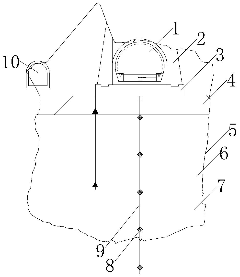
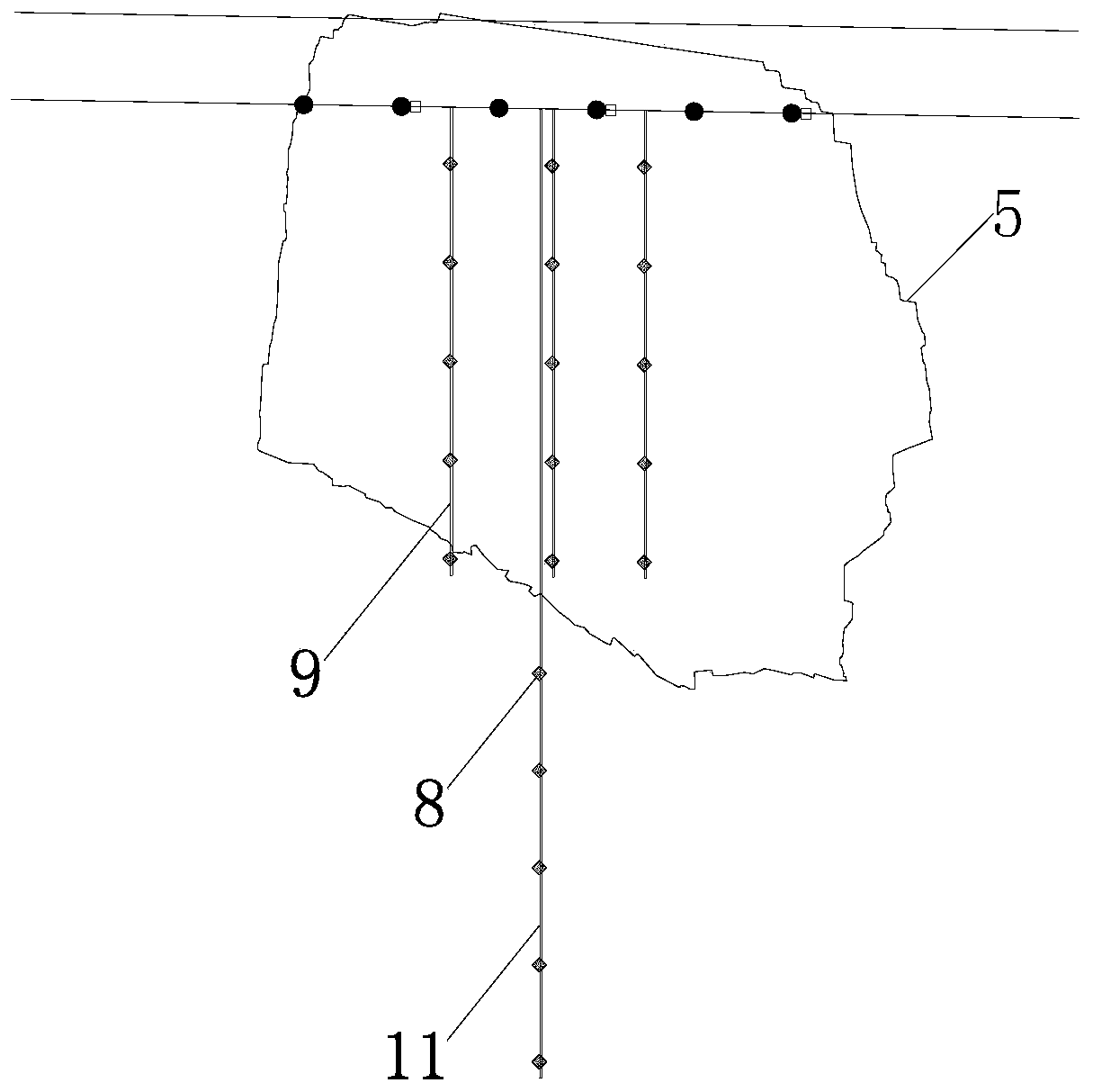
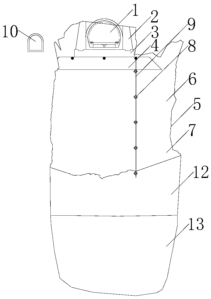
The invention discloses a backfilling treatment construction method for a tunnel high crossing giant salt cavern. The bottom of a karst cave is processed; the karst cave is subjected to backfilling treatment through a construction guide hole, the karst cave is filled to a height which is flush with the level of the construction guide hole, and a layer of grout stop plate is constructed; backfill is dumped from hole entrances of two sides of a tunnel main hole and an entrance of pilot heading in the cave, and the backfill is back-filled to the bottom elevation of a main hole entrance; groutingand subsidence reducing are conducted on the backfill, and standing is conducted for a while after grouting; the top of the backfill is subjected to the construction of a cement graded crushed rock layer; after the construction completion of the graded crushed rock layer, drilling holes are formed in the karst cave backfill and bottom deposit settlement monitoring points, settlement monitoring isstarted, and standing is conducted for a period of time until monitoring data shows the settlement is stable; after monitoring shows that the settlement is stable and design requirements are met, a concrete road substrate is started to be constructed, large side walls are constructed on both sides of the concrete road substrate, outer karst caves of the large side walls continue to be back-filledby ordinary hole ballasts, an inner side is constructed as a tunnel open cut tunnel structure, and the entire karst cave process is completed.

Description

technical field [0001] The invention belongs to the field of solution cavity treatment, and in particular relates to a backfill treatment construction method for a tunnel passing through a giant solution cavity at a high position. Background technique [0002] The statements herein merely provide background information related to the present invention and do not necessarily constitute prior art. [0003] With the development of tunnel construction technology, the construction is faced with a variety of complex terrain and landforms, especially in the tunnels built in Southwest China, which often expose large dissolved cavities. Most of the existing solution cavity treatment technologies are aimed at small and medium-sized solution cavities, and there is currently a lack of mature construction treatment methods for large solution cavities that pass through high tunnels; existing large solution cavities are mostly backfilled by concrete pouring. The cost of the method is very...

Claims


Application Information

Patent Timeline
Patent Type & Authority Patents(China)
IPC IPC(8): E21D9/00E21D11/10
Inventor 孙亚飞于明洋隋渤海朱桂利王孝波李占先刘利王军
Owner 中铁十四局集团建筑工程有限公司
Learn More