Control method of fan wall and fan wall

A control method and fan wall technology, applied in the field of control, can solve problems such as different speeds between fans, unstable fan speeds, and lower overall operating efficiency of the fan wall, so as to achieve stable speeds, reduce mutual interference, and protect fans.

Active Publication Date: 2019-04-16
ZHEJIANG MINGZHEN ELECTRIC&ELECTRONICS CO LTD +1
View PDF9 Cites 1 Cited by
  • Summary
  • Abstract
  • Description
  • Claims
  • Application Information

AI Technical Summary

Problems solved by technology

With this control method, the speed of each fan is unstable, and because of the different speeds of the fans, there is interference with each other, which reduces the overall operating efficiency of the fan wall.

Method used


Image

  • Control method of fan wall and fan wall
  • Control method of fan wall and fan wall
  • Control method of fan wall and fan wall

Examples


Embodiment 1

[0022] This embodiment provides a method for controlling a fan wall, including the following steps:

[0023] During the operation of the fan wall, the control host collects the wind pressure at the outlet of any fan through the wind pressure sensor, and compares it with the atmospheric pressure to obtain the first pressure difference ΔP1=P 风口 -P 大气压 ; At the same time, the control host obtains the second pressure difference ΔP2=(Q / (n×k))^2 through calculation, where Q is

[0024] The set fan air volume, n is the number of fans in the fan wall, and k is the attribute coefficient of the fan itself, which is related to the diameter of the fan rotor. The specific corresponding relationship is as follows:

[0025] Wind wheel diameter

250

280

310

355

400

450

500

560

630

710

800

900

k value

76

77

116

148

188

240

281

348

438

545

695

900

[0026] Furthermore, during the operation of the fan w...

Embodiment 2

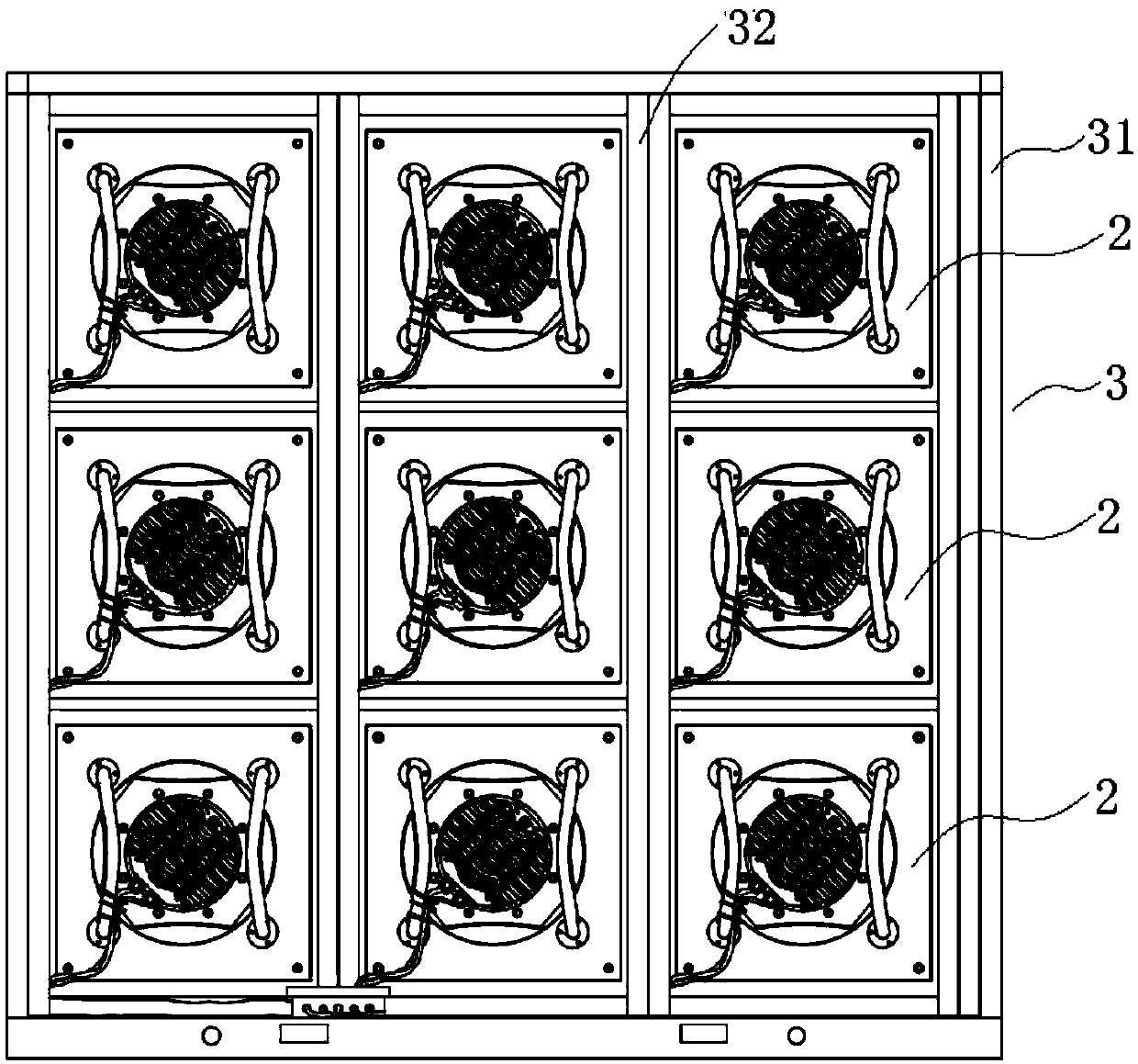
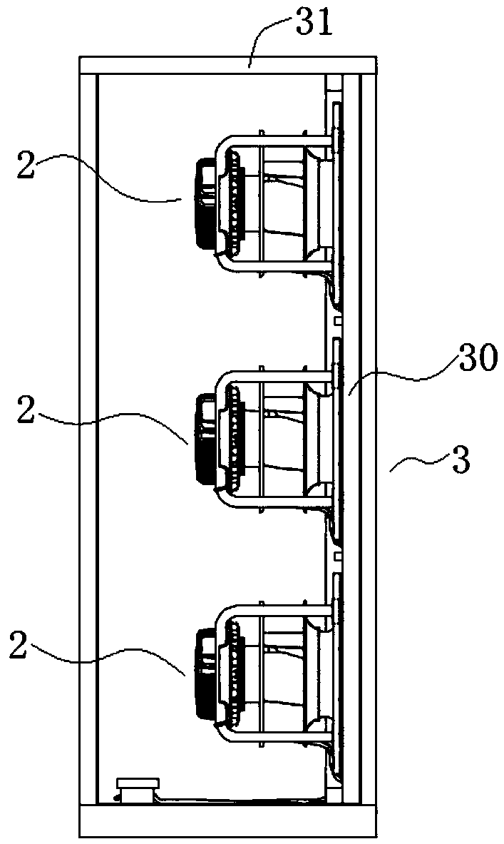
[0030] This embodiment provides a fan wall, such as Figure 1-2 As shown, it includes a fan wall frame 3 and several fans 2 installed in the fan wall frame. Wherein, the fan wall frame 3 includes a front wall 30 for installing a fan and a side wall 31 surrounding the front wall 30 to form a semi-closed cavity. The front wall 30 is provided with an opening corresponding to the air inlet of the fan. In order to enhance the reliability of the fan wall as a whole, several reinforcing ribs 32 are arranged at intervals on the side where the fan is installed on the front wall 30 .

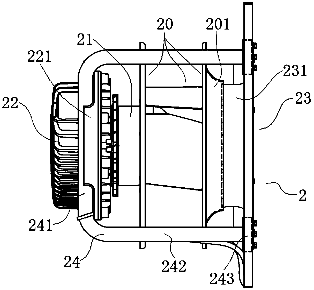
[0031] Such as image 3 As shown, the fan is a DC brushless fan, including a coaxially connected wind wheel 20 , a motor 21 , a motor driver 22 , a front panel 23 and fasteners 24 . The motor 21 is connected to the wind wheel 20 through the motor flange, the front panel 23 is provided with an inwardly extending air vent 231 , and the side of the wind wheel 20 away from the motor is provided with an air ...


PUM


Abstract

The invention provides a control method of a fan wall. The control method comprises the following steps that S1, a main engine is controlled to collect the air pressure of an air opening of any fan through an air pressure sensor, the air pressure is compared with barometric pressure, and a first pressure difference delta P1 is equal to P<air opening>-P<barometric pressure>; S2, the main engine iscontrolled to obtain a second pressure difference delta P2 equal to (Q / (n*k)^2), wherein Q is the set fan air volume, n is the number of the fans of the fan wall, and k is the fan attribute coefficients; and S3, the main engine is controlled to adjust the air openings P by controlling the rotating speed of the fans, the rotating speed of all the fans is consistent, and the condition that delta P1-delta P2 is kept. According to the control method, the fans are controlled in a control manner of controlling the torque, all the fans stably operate together, and interference between the fans is reduced.

Description

technical field [0001] The invention relates to the technical field of control, in particular to a method for controlling a fan wall and a fan wall controlled by the method. Background technique [0002] The fan wall is a wall composed of multiple fans, replacing the role of one large fan with multiple small fans to reduce the overall equipment volume. The control mode of the existing fan wall is as follows: multiple fans operate independently, and the speed of each fan is adjusted based on a preset value. With this control method, the speed of each fan is unstable, and the fans interfere with each other because of the different speeds, thereby reducing the overall operating efficiency of the fan wall. Contents of the invention [0003] The purpose of the present invention is to provide a fan wall control method, which controls the fans by controlling the torque, so that all the fans can run stably together and reduce the mutual interference between the fans. [0004] In...

Claims


Application Information

Patent Timeline
IPC IPC(8): F04D27/00F04D25/08F04D25/16H02K7/14
CPCF04D25/0606F04D25/08F04D25/166F04D27/004F05D2270/3013F05D2270/3015F05D2270/705H02K7/14
Inventor 陈洪星刘国雷
Owner ZHEJIANG MINGZHEN ELECTRIC&ELECTRONICS CO LTD
Why Eureka
Try Eureka