Phase contrast microscope and debugging method thereof

A phase-contrast microscope and phase-contrast technology, applied in microscopes, optics, instruments, etc., can solve the problems of poor microscope display and achieve the effects of expanded illumination numerical aperture, high display resolution, and good illumination effects

Active Publication Date: 2019-04-16
NINGBO SUNNY INSTR
View PDF5 Cites 1 Cited by
  • Summary
  • Abstract
  • Description
  • Claims
  • Application Information

AI Technical Summary

Problems solved by technology

[0005] The purpose of the present invention is to provide a phase contrast micr

Method used


Image

  • Phase contrast microscope and debugging method thereof
  • Phase contrast microscope and debugging method thereof
  • Phase contrast microscope and debugging method thereof

Examples


Embodiment approach

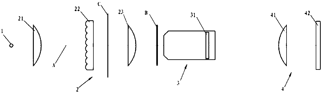
[0033] Such as figure 1 As shown, according to an embodiment of the present invention, the light source 1 is a luminous body.

[0034] Such as figure 1 As shown, according to an embodiment of the present invention, the illumination processing unit 2 includes a condenser lens 21 , a fly-eye lens 22 and a condenser lens 23 sequentially arranged along the light transmission direction. In this embodiment, the light source 1 and the collecting mirror 21 are on the same optical axis A, and the collecting mirror 21 has a collimating function, and the light emitted by the light source 1 becomes collimated light after being collimated by the collecting mirror 21 (i.e. The light emitted by the light source 1 is parallel light), and then the output of the collimated light of the light source 1 is realized. In this embodiment, the fly-eye lens 22 is located between the condenser lens 21 and the condenser lens 23 . The collimated light generated by the condenser lens 21 sequentially pas...


PUM


Abstract

The invention relates to a phase contrast microscope and a debugging method thereof. The phase contrast microscope comprises a light source (1), an illumination processing unit (2), an objective lensunit (3) and an imaging unit (4) which are arranged in sequence along the light transmission direction, wherein the illumination processing unit (2) includes a light collecting mirror (21), a fly eyelens (22) and a light condensing mirror (23) which are arranged in sequence along the light transmission direction; the objective lens unit (3) is provided with a phase contrast board (31), and the phase contrast board (31) is a spotted phase contrast board. The phase contrast microscope can achieve the effects of high resolution, high illumination efficiency and ability of being free of shallow and halation through adopting the spotted phase contrast board.

Description

technical field [0001] The invention relates to a microscope and a debugging method thereof, in particular to a phase contrast microscope and a debugging method thereof. Background technique [0002] In the process of biological cell detection, biological cell specimens usually lack the difference in transmittance, and these specimens can hardly see any cell information when observed with bright field illumination. The phase contrast technology makes use of the difference in refractive index and thickness of different parts of biological cell specimens, and makes almost transparent cell specimens Create contrast. Therefore, compared with the general bright field microscope, the microscope using phase contrast technology has made the following adjustments: an annular diaphragm is placed near the aperture diaphragm, and a phase contrast plate is placed at the position conjugate to the annular diaphragm in the microscope objective lens . The part of the phase contrast plate ...

Claims


Application Information

Patent Timeline
IPC IPC(8): G02B21/00G02B21/02G02B21/26
CPCG02B21/0004G02B21/02G02B21/26
Inventor 孙长胜李伸朋仝飞
Owner NINGBO SUNNY INSTR
Why Eureka
Try Eureka