Equipment capable of carrying out image recording in airtight aqueous pipeline
What is Al technical title?
Al technical title is built by PatSnap Al team. It summarizes the technical point description of the patent document.
A technology for pipelines and equipment, applied in the field of video recording equipment in pipelines, can solve the problems of cameras that cannot be cleaned, cannot work, and have low power.
Inactive Publication Date: 2019-04-16
保定市尚泉供水有限公司
View PDF9 Cites 0 Cited by
Summary
Abstract
Description
Claims
Application Information
AI Technical Summary
This helps you quickly interpret patents by identifying the three key elements:
Problems solved by technology
Method used
Benefits of technology
Problems solved by technology
[0002] Due to the continuous growth of my country's urban population, there are more and more problems in water supply, drainage, and sewage pipes. The sediment accumulated in the pipeline for many years and the debris left in the pipeline construction may change direction and accumulate together to form pipeline blockage, water quality decline, and cause hidden dangers. After the construction is completed, a robot inspection must be carried out inside the pipeline. Then flush the inside of the pipeline, and it will be more difficult to repair the normal water supply pipeline.
[0003] The structure of the existing mounting bracket is relatively simple. First, the traditional equipment uses two driving wheels with low power and cannot work in harsh environments. Second, the traditional equipment is not equipped with a trapping device. When the equipment cannot be moved due to harsh environments, Can only wait for rescue, and the rescue cost is high. Third, traditional equipment adopts traditional control, which makes the equipment bulky and cumbersome. Fourth, traditional equipment cannot clean up the camera of the equipment during operation, and must return when the camera cannot see clearly.
Method used
Image
Click on the blue label to locate the original text in one second.
Reading with bidirectional positioning of images and text.
Examples
Embodiment Construction
[0018] The following will clearly and completely describe the technical solutions in the embodiments of the present invention with reference to the accompanying drawings in the embodiments of the present invention. Obviously, the described embodiments are only some, not all, embodiments of the present invention. Based on the embodiments of the present invention, all other embodiments obtained by persons of ordinary skill in the art without making creative efforts belong to the protection scope of the present invention.
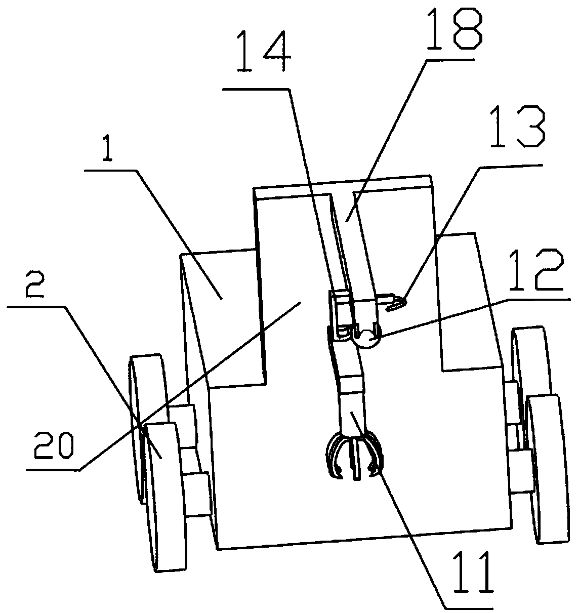
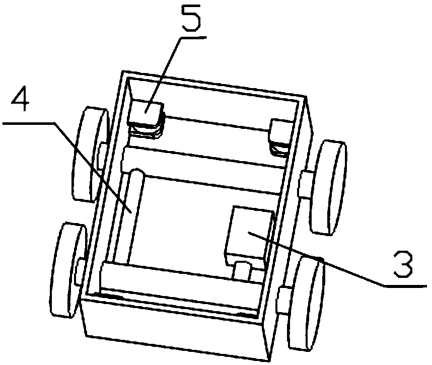
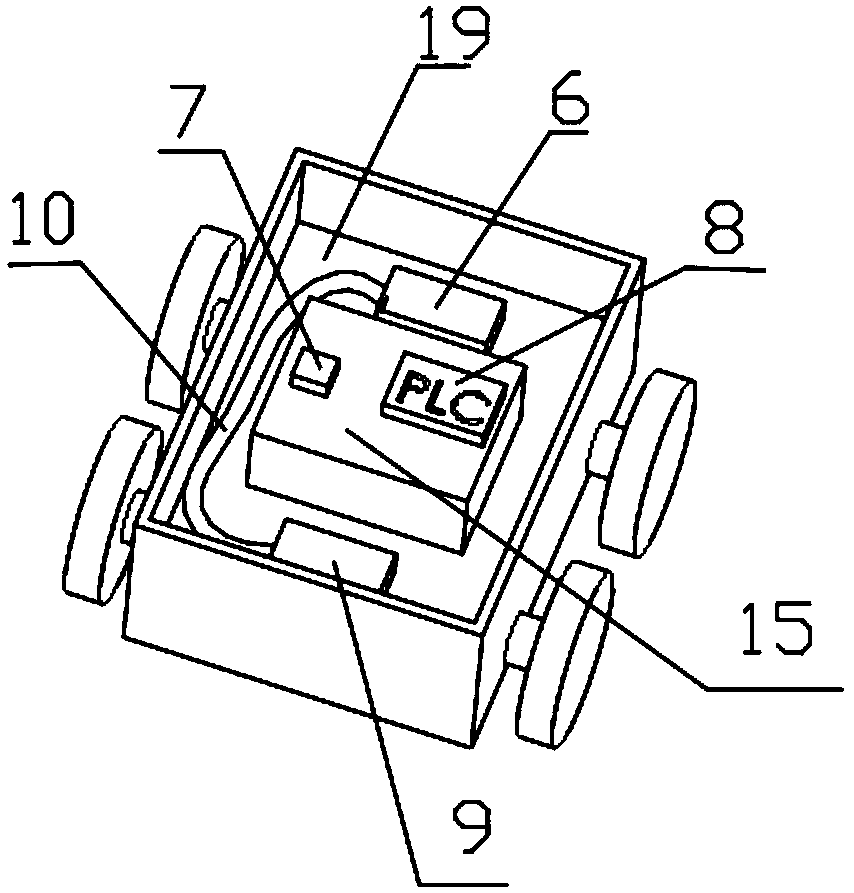
[0019] see Figure 1~4 , an image recording device capable of recording images in a closed pipeline with water, comprising a main box 1, a driving wheel 2, a motor 3, a power transmission shaft 4, a cylinder 5, a water tank 6, a GPS positioning system 7, a PLC control system 8, Spare water tank 9, water pipe 10, obstacle removal gripper 11, camera 12, cleaning pipe 13, cleaning claw 14, battery case 15, rotating shaft 16, camera base 17, support 18, intermedia...
PUM
Abstract
The invention discloses equipment capable of carrying out image recording in an airtight aqueous pipeline. The equipment comprises a host case, drive wheels, a motor, a power transmission shaft, cylinders, a water tank, a GPS, a PLC control system, a standby water tank, a water pipe, an obstacle clearing gripper, a camera, a cleaning pipe, a cleaning claw, a storage battery box, a rotation shaft,a camera base, a holder, an intermediate clapboard and a multifunctional board. The equipment has the beneficial effects that the drive wheels are connected with the motor through utilization of the power transmission shaft; the equipment is equipped with four drive wheels, so drive power is improved; through 4-wheel drive, the equipment is applicable to many severe environments; the cleaning pipeand the cleaning claw are fastened at two sides of the holder through bolts, so a surface of the camera of the camera can be automatically cleaned when the camera works; working efficiency of the equipment is greatly improved; and the obstacle clearing gripper is fixed at a front end of the multifunctional board through utilization of a moving mechanism and the obstacle clearing gripper can act through utilization of a remote system, so the equipment operates relatively conveniently in the severe environments, and working reliability of the equipment is greatly improved.
Description
technical field [0001] The invention relates to an image recording device in a pipeline, in particular to an image recording device capable of recording images in a watertight pipeline, and belongs to the technical field of construction in a pipeline. Background technique [0002] Due to the continuous growth of my country's urban population, there are more and more problems in water supply, drainage, and sewage pipes. The sediment accumulated in the pipeline for many years and the debris left in the pipeline construction may change direction and accumulate together to form pipeline blockage, water quality decline, and cause hidden dangers. After the construction is completed, a robot inspection must be carried out inside the pipeline. Flush in the pipeline again, the overhaul of normal water supply pipeline is just more difficult. [0003] The structure of the existing mounting bracket is relatively simple. First, the traditional equipment uses two driving wheels with low po...
Claims
Application Information
Patent Timeline
Application Date:The date an application was filed.
Publication Date:The date a patent or application was officially published.
First Publication Date:The earliest publication date of a patent with the same application number.
Issue Date:Publication date of the patent grant document.
PCT Entry Date:The Entry date of PCT National Phase.
Estimated Expiry Date:The statutory expiry date of a patent right according to the Patent Law, and it is the longest term of protection that the patent right can achieve without the termination of the patent right due to other reasons(Term extension factor has been taken into account ).
Invalid Date:Actual expiry date is based on effective date or publication date of legal transaction data of invalid patent.