Communication method and device
A communication device and communication connection technology, which is applied in the field of visual networking, can solve the problems that the alarm equipment cannot carry out real-time video communication, and the on-site personnel cannot be evacuated or evacuated.
- Summary
- Abstract
- Description
- Claims
- Application Information
AI Technical Summary
Problems solved by technology
Method used
Image

Examples
Embodiment Construction
[0051] In order to make the above objects, features and advantages of the present application more obvious and comprehensible, the present application will be further described in detail below in conjunction with the accompanying drawings and specific implementation methods.
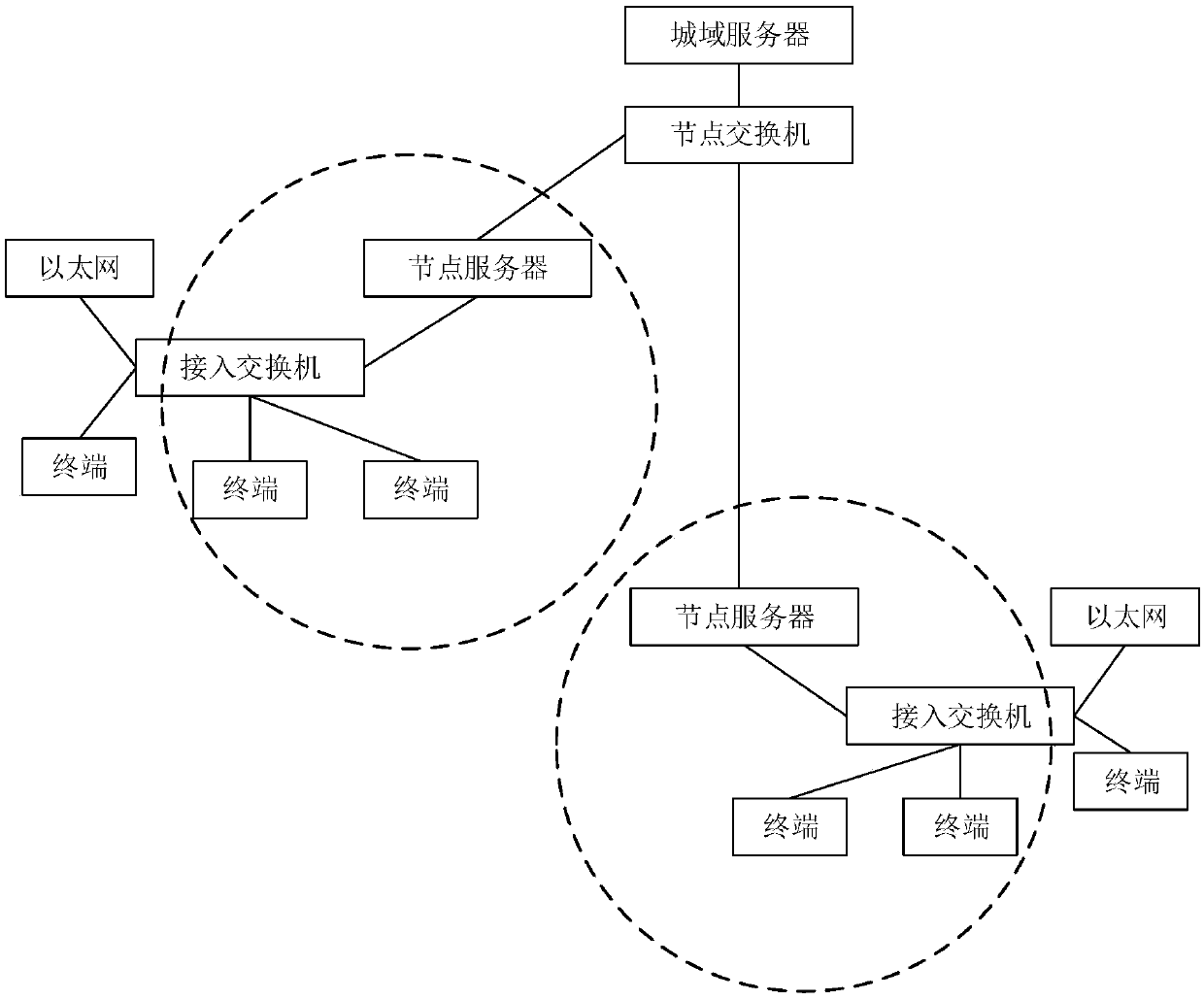
[0052] The Internet of Vision is an important milestone in the development of the network. It is a real-time network that can realize real-time transmission of high-definition video, and push many Internet applications to high-definition video, high-definition face-to-face.
[0053] The Internet of View adopts real-time high-definition video exchange technology, which can provide required services on one network platform, such as high-definition video conferencing, video surveillance, intelligent monitoring and analysis, emergency command, digital broadcast TV, time-lapse TV, online teaching, live broadcast , VOD on demand, TV mail, personalized recording (PVR), intranet (self-managed) channel, intelligen...
PUM
 Abstract
Description
Claims
Application Information
 - Generate Ideas
- Intellectual Property
- Life Sciences
- Materials
- Tech Scout
- Unparalleled Data Quality
- Higher Quality Content
- 60% Fewer Hallucinations
Browse by: Latest US Patents, China's latest patents, Technical Efficacy Thesaurus, Application Domain, Technology Topic, Popular Technical Reports.
© 2025 PatSnap. All rights reserved.Legal|Privacy policy|Modern Slavery Act Transparency Statement|Sitemap|About US| Contact US: help@patsnap.com