Micro base station, and power supply control method of micro base station

A technology of power supply control and micro base station, which is applied in the field of communication, can solve the problems of power consumption, waste of power, excessive noise, etc., and achieve the effect of prolonging working hours, reducing power consumption and prolonging service life

Active Publication Date: 2019-04-16
WUHAN HONGXIN TELECOMM TECH CO LTD
View PDF14 Cites 1 Cited by
  • Summary
  • Abstract
  • Description
  • Claims
  • Application Information

AI Technical Summary

Problems solved by technology

In the existing multi-standard multi-frequency point vehicle-mounted micro base station, either do not perform power control, and directly power on and run the whole module with one button; or set many switch buttons, and then manually turn on or off the corresponding switch according to different standards and different frequency points. There is artificial arbitrariness, and there is inevitably a waste of power
Therefore, there is a large waste of power in the existing multi-standard and multi-frequency point micro base stations, and the battery power lacks real-time monitoring, and there is no early warning mechanism; the cooling fan runs at full speed when it is powered on, which not only consumes power, but also causes long-term noise in the car exceed the standard

Method used


Image

  • Micro base station, and power supply control method of micro base station
  • Micro base station, and power supply control method of micro base station
  • Micro base station, and power supply control method of micro base station

Examples


Embodiment Construction

[0027] In order to make the purpose, technical solutions and advantages of the embodiments of the present invention clearer, the technical solutions in the embodiments of the present invention will be clearly and completely described below in conjunction with the drawings in the embodiments of the present invention. Obviously, the described embodiments It is a part of embodiments of the present invention, but not all embodiments. The embodiments of the present invention and all other embodiments obtained by persons of ordinary skill in the art without creative efforts all belong to the protection scope of the present invention.

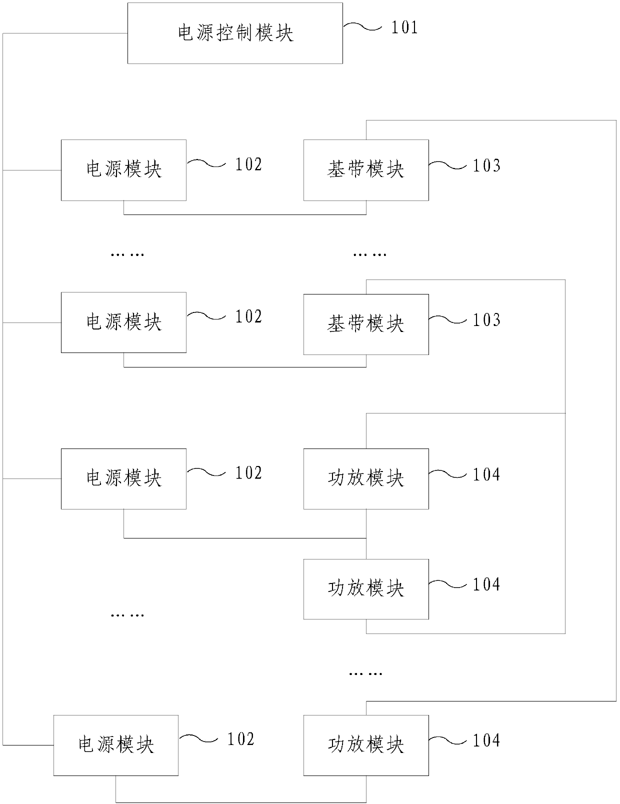
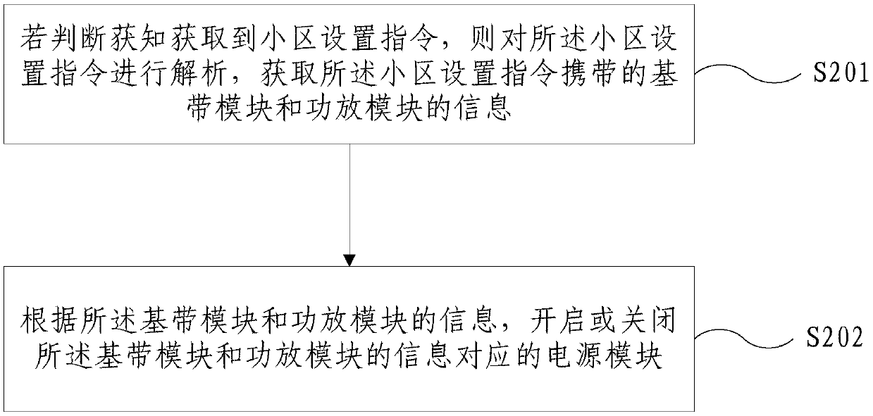
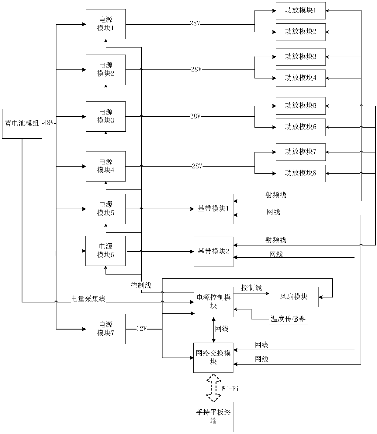
[0028] In order to overcome the above-mentioned problems in the prior art, an embodiment of the present invention provides a micro base station and a power supply control method for the micro base station. module or power amplifier module to work or stop working.

[0029] figure 1 It is a schematic structural diagram of a micro base station provided...


PUM


Abstract

The embodiment of the invention provides a micro base station, and a power supply control method of the micro base station. The micro base station comprises a power supply control module, a pluralityof power supply modules, a plurality of baseband modules, and a plurality of power amplifier modules; the power supply control module is used for obtaining a cell setting instruction, parsing the cellsetting instruction to obtain the information of the baseband modules and the power amplifier modules carried in the cell setting instruction, and turning on or turning off the power supply modules corresponding to the information of the baseband modules and the power amplifier modules according to the information of the baseband modules and the power amplifier modules; the power supply modules are used for providing electric energy for the baseband modules or the power amplifier modules connected with the power supply control module; and the baseband modules and the power amplifier modules are used for working according to the cell setting instruction. According to the micro base station, and the power supply control method of the micro base station provided by the embodiment of the invention, by parsing the cell setting instruction via the power supply control module, the corresponding power supply modules are turned on or turned off, thereby reducing the waste of the electric energy and prolonging the endurance time of the micro base station.

Description

technical field [0001] Embodiments of the present invention relate to the field of communication technologies, and in particular, to a micro base station and a method for controlling power supply of the micro base station. Background technique [0002] With the rapid development of mobile communications and the popularization of mobile phones, there has always been a need for positioning through base stations or suppressing communications in a certain area. In the current market, active positioning or communication suppression equipment for communication standards such as GSM, TD-SCDMA, and WCDMA has been widely used. Staying in the 4G network, multi-standard multi-frequency base stations came into being. [0003] Multi-mode and multi-frequency base stations are usually small in size, so they can be called micro base stations, and can be implemented in vehicles. In the existing multi-standard multi-frequency point vehicle-mounted micro base station, either do not perform p...

Claims


Application Information

Patent Timeline
Patent Type & Authority Applications(China)
IPC IPC(8): H04W52/02H04W88/10
CPCH04W52/0225H04W52/0274H04W52/028H04W88/10Y02D30/70
Inventor 朱应波高金萍湛秀平
Owner WUHAN HONGXIN TELECOMM TECH CO LTD
Why Eureka
Try Eureka