
Construction waste sorting device

A sorting device and technology for construction waste, applied in grain processing, etc., can solve problems such as incomplete functions and no way to separate construction waste

Active Publication Date: 2019-04-19
吉林省嘉元绿宝环卫设备股份有限公司
View PDF5 Cites 2 Cited by
  • Summary
  • Abstract
  • Description
  • Claims
  • Application Information

AI Technical Summary

Problems solved by technology

[0002] For example, the patent number is CN201820384202.4 a kind of construction waste sorting device, its structure includes waste sorting port, support feet, lower support platform, generator, guard rod, fixed block, construction waste crushing device, observation window, bracket, bearing platform, Fixed rod, two supporting legs are provided horizontally and welded vertically to the lower end of the bearing platform. The fixed rod is a cuboid structure and the two ends are welded to the supporting legs. A construction waste crushing device is installed on the structure, and the construction waste is passed through the feeding port Pour in, and then use the rotating rod and the garbage shredder to rotate at high speed to crush the construction waste, and then the falling debris will be processed again through the electromagnetic crushing rod, and the uncrushable ones will be directly conveyed to the conveyor belt through the conveying block and passed through The garbage sorting port is used for discharge, but the disadvantage of this invention is that there is no way to separate the crushed construction waste, and the function is not complete

Method used


Image

  • Construction waste sorting device
  • Construction waste sorting device
  • Construction waste sorting device

Examples


specific Embodiment approach 1

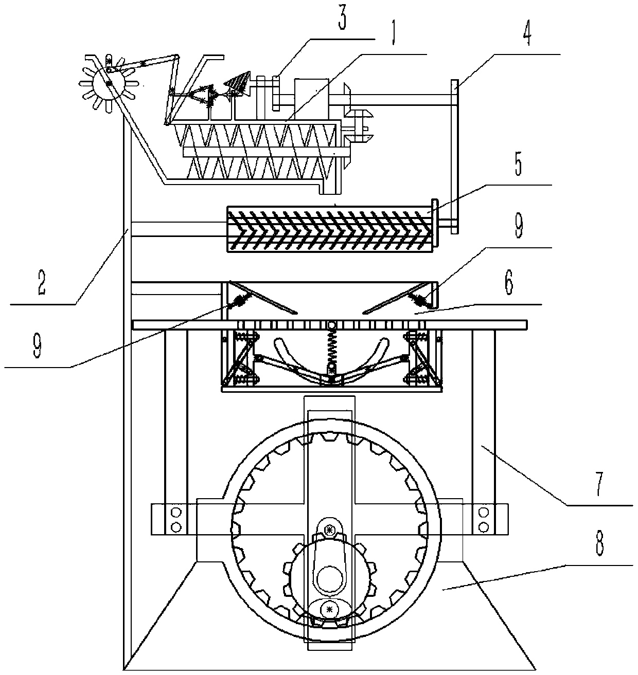
[0031] Combine below Figure 1-13 Describe this embodiment, a construction waste sorting device, including a transmission device 1, an outer fixed frame 2, a transmission belt 3, a transmission belt 2 4, a crushing device 5, a separation device 6, a mobile fixing frame 7, a lower turret 8 and a reset Push the combination 9, the transmission device 1 is fixedly connected with the outer fixed frame 2, the transmission belt 1 3 is connected with the transmission device 1 with interference fit, the transmission belt 2 4 is connected between the transmission device 1 and the crushing device 5, and the crushing device 5 is fixed to the outside The frame 2 is fixedly connected, the separation device 6 is fixedly connected with the outer fixed frame 2, the mobile fixed frame 7 is fixedly connected with the separation device 6, the lower turntable 8 is fixedly connected with the outer fixed frame 2, and the reset push combination 9 is hingedly connected with the separation device 6 . ...

specific Embodiment approach 2

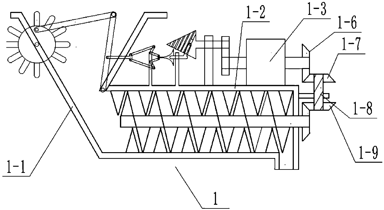
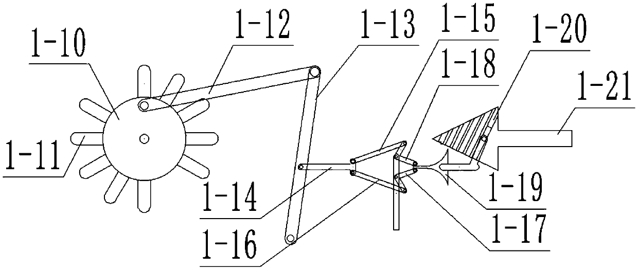
[0032] Combine below Figure 1-13 Describe this embodiment, this embodiment will further explain Embodiment 1, the transmission device 1 includes a transmission device outer frame 1-1, an upper side wall plate 1-2, a biaxial motor 1-3, and an output bevel gear 1-6 , Transmission bevel gear 1-7, transmission shaft 1-8, transmission bevel gear 2 1-9, dial 1-10, dial lever 1-11, middle connecting rod 1-12, hinged push rod 1- 13. Horizontal sliding rod 1-14, hinged connecting rod one 1-15, hinged connecting rod two 1-16, hinged connecting rod three 1-17, hinged connecting rod four 1-18, fader 1-19, spiral chute 1-20 and a rotating cone rod 1-21, the transmission device outer frame 1-1 includes a transmission device outer frame body 1-1-1, an inner hollow cavity 1-1-2, a fixed plate 1-1-3 , fixed plate 2 1-1-4, right end rotating hole 1-1-5, rotating shaft 1-1-6 with spiral leaves, outer frame discharge port 1-1-7 and rotating shaft bevel gear 1-1-8, The hollow cavity 1-1-2 at th...

specific Embodiment approach 3

[0034] Combine below Figure 1-13 This embodiment will be described. This embodiment will further describe Embodiment 1. The crushing device 5 includes a crushing device outer frame 5-1, a sun gear 5-2, a sun gear shaft 5-3, a crushing shaft 5-4, and a crushing device. Shaft 2 5-5, planetary gear 3 5-6, planetary gear 1 5-7, planetary gear 2 5-8, intermediate runner 5-9, crushing device hollow cavity 5-10, crushing shaft 3 5-11 and crushing The discharge port 5-12 of the device, the sun gear 5-2 is arranged at the right end of the crushing device outer frame 5-1, the sun gear rotating shaft 5-3 is rotationally connected with the crushing device outer frame 5-1, and the sun gear 5-2 is fixedly connected to the The left end of the sun wheel rotating shaft 5-3, the crushing shaft one 5-4 is rotatably connected in the crushing device outer frame 5-1, the crushing shaft two 5-5 is rotatably connected in the crushing device frame 5-1, and the crushing shaft three 5- 11 Rotationally...


PUM


Abstract

The invention relates to a construction engineering machine, in particular to a construction waste sorting device. The device is provided with a dial wheel, and splash of construction waste can be prevented by driving of a middle end connecting rod. A crushing device is arranged, and mutual extrusion between crushing shafts facilitates crushing of the construction waste. The crushed waste can be separated through a separating device. The construction waste sorting device comprises a conveying device, an outer side fixing frame, a first driving belt, a second driving belt, the crushing device,the separating device, a movable fixing frame, a lower side rotary frame and a reset push combination. A rotary cone rod can be conveniently rotationally connected with a second fixing plate, the first driving belt can be conveniently connected to the rotary cone rod and an output shaft at the left end of a dual-shaft motor, the upper end of the outer side fixing frame can be conveniently fixedlyconnected to an outer frame body of the conveying device, a hollow cavity of the crushing device can be conveniently arranged at the inner end of the outer frame of the crushing device, and a discharge outlet of the crushing device can be conveniently arranged at the lower end of the outer frame of the crushing device.

Description

technical field [0001] The invention relates to a construction engineering machine, more specifically to a construction waste sorting device. Background technique [0002] For example, the patent number is CN201820384202.4 a kind of construction waste sorting device, its structure includes waste sorting port, support feet, lower support platform, generator, guard rod, fixed block, construction waste crushing device, observation window, bracket, bearing platform, Fixed rod, two supporting legs are provided horizontally and welded vertically to the lower end of the bearing platform. The fixed rod is a cuboid structure and the two ends are welded to the supporting legs. A construction waste crushing device is installed on the structure, and the construction waste is passed through the feeding port Pour in, and then use the rotating rod and the garbage shredder to rotate at high speed to crush the construction waste, and then the falling debris will be processed again through th...

Claims


Application Information

Patent Timeline
Patent Type & Authority Applications(China)
IPC IPC(8): B02C4/08B02C4/28B02C4/42B02C23/10B02C23/02
CPCB02C4/08B02C4/286B02C4/42B02C23/02B02C23/10B02C2201/02B02C2201/06
Inventor 张建华
Owner 吉林省嘉元绿宝环卫设备股份有限公司
Learn More