Rotatable mechanical gripper device

A technology of rotating manipulators and manipulators, applied in metal processing and other directions, can solve the problems of workpiece clamping, inability to realize, and inability to realize the horizontal exchange of two claws, etc., to achieve the effect of high processing efficiency

Pending Publication Date: 2019-04-19
宁波开浦智能科技有限公司
View PDF19 Cites 3 Cited by
  • Summary
  • Abstract
  • Description
  • Claims
  • Application Information

AI Technical Summary

Problems solved by technology

[0003] For example, the invention patent with application number 201710639935.8 discloses a swing-type rotary air claw device, and the invention patent with application number 201710647581.1 discloses a manipulator rotary air claw device. Swing in the plane, the mechanical rotating gripper device can realize the swing of the two air grippers in the three-dimensional space, but these two kinds of air gripper devices can only realize the exchange of the two grippers in the vertical and horizontal directions, that is, the vertical workpiece and the horizontal The replacement of workpieces cannot realize the replacement of the two claws in the horizontal direction. When the existing processing equipment needs the workpiece to be replaced in the horizontal direction, the air gripper devices of the above two structures cannot realize this function; in addition, when the workpiece is heavy And when two claws are required to be clamped at the same time, the above two structures cannot clamp the workpiece at the same time

Method used


Image

  • Rotatable mechanical gripper device
  • Rotatable mechanical gripper device
  • Rotatable mechanical gripper device

Examples


Embodiment Construction

[0050] The following are specific embodiments of the present invention and in conjunction with the accompanying drawings, further describe the technical solution of the present invention, but the present invention is not limited to these embodiments.

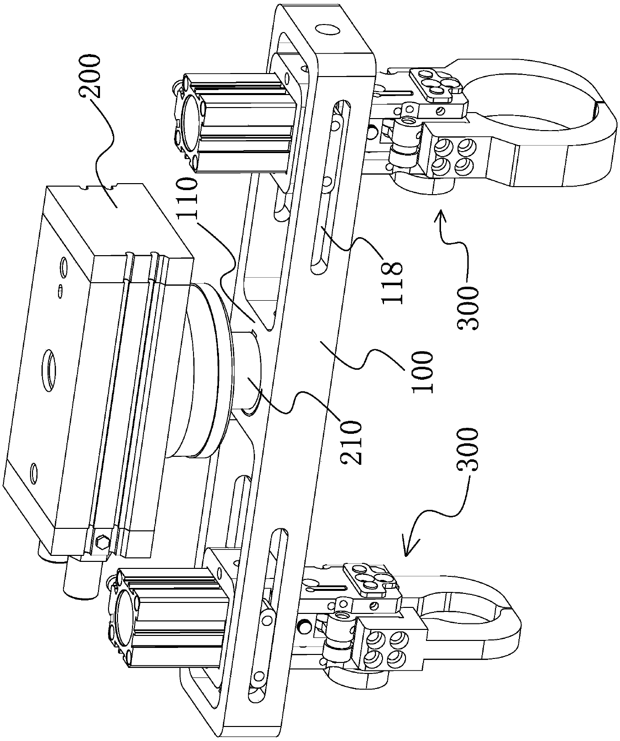
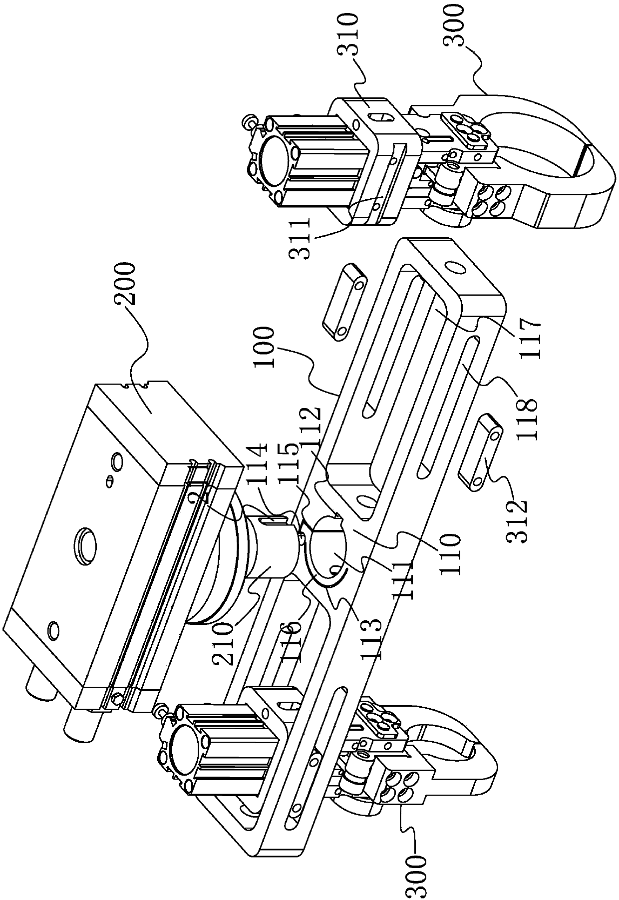
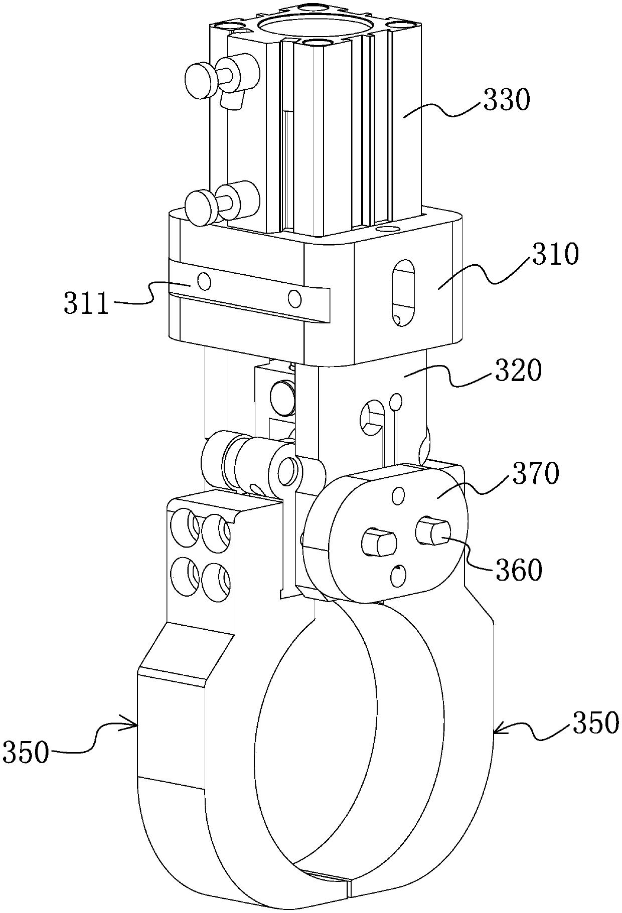
[0051] Such as figure 1 , figure 2 As shown, a rotatable manipulator 300 device of the present invention includes a frame 100 , a rotary cylinder 200 and a manipulator 300 .

[0052] The frame 100 is axially and horizontally arranged, the middle part of the frame 100 has a mounting plate 110, the output shaft 210 of the rotary cylinder 200 is fixedly connected with the mounting plate 110, and there are two groups of mechanical claws 300, preferably, each group has a mechanical claw 300 , the two manipulator claws 300 are respectively movably connected with the two ends of the frame 100, and the two sets of manipulator claws 300 are coaxially arranged and can hold workpieces. When working, the rotary cylinder 200 can drive the ...


PUM


Abstract

The invention provides a rotatable mechanical gripper device, and belongs to the technical field of mechanical grippers. The technical problem that an existing pneumatic gripper device cannot achievethe effect that two grippers are switched in the horizontal plane is solved. The rotatable mechanical gripper device comprises a machine frame, a rotation air cylinder and two mechanical grippers, wherein the machine frame is horizontally arranged; an output shaft of the rotation air cylinder is fixedly connected with the middle of the machine frame; the two mechanical grippers are movably connected with the two ends of the machine frame, are coaxially arranged and can clamp and place workpieces; the rotation air cylinder can drive the machine frame to horizontally rotate within the preset angle, and the two mechanical grippers can synchronously move along with rotation of the machine frame; and the two mechanical grippers are simultaneously installed on the horizontally-arranged machine frame, the machine frame is driven to rotate through the rotation air cylinder, then, switching of the two mechanical grippers in the horizontal direction can be achieved, and accordingly, workpieces can be rotated in the horizontal direction.

Description

technical field [0001] The invention belongs to the technical field of mechanical grippers, and relates to a rotatable mechanical gripper device. Background technique [0002] Manipulator claws are commonly used mechanical parts in machining equipment at present, especially for the processing of shaft workpieces. Generally, different manipulator claws need to be designed according to different processing techniques and processing requirements. For the processing of shaft workpieces, common manipulators The jaw is a two-jaw pneumatic jaw structure. [0003] For example, the invention patent with application number 201710639935.8 discloses a swing-type rotary air claw device, and the invention patent with application number 201710647581.1 discloses a manipulator rotary air claw device. Swing in the plane, the mechanical rotating gripper device can realize the swing of the two air grippers in the three-dimensional space, but these two kinds of air gripper devices can only real...

Claims


Application Information

Patent Timeline
Patent Type & Authority Applications(China)
IPC IPC(8): B23Q7/04
CPCB23Q7/043B23Q7/048
Inventor 杨云林
Owner 宁波开浦智能科技有限公司
Why Eureka
Try Eureka