Quantitative valve assembly

A technology of quantitative valves and components, applied in the direction of lift valves, valve devices, engine components, etc., can solve the problems of tediousness, affecting the taste and beauty of dishes, wasting time and energy, etc., and achieve the effect of convenient and simple use

Pending Publication Date: 2019-04-19
梁桉滔
View PDF0 Cites 0 Cited by
  • Summary
  • Abstract
  • Description
  • Claims
  • Application Information

AI Technical Summary

Problems solved by technology

[0004] This way of pouring out each time requires the cooking staff to slowly pour out the bottle to control the amount of pouring out. In this way, when the novice or the hand shakes, the amount of liquid poured out is difficult to control, and the liquid condiment poured out each time The amount is also different, more or less will affect the taste and aesthetics of the dishes
[0005] The traditional method is to pour the seasoning into the measuring cup and use the measuring cup to measure. This method is cumbersome, and the measuring cup needs to be washed before and after use, which wastes time and energy

Method used


Image

  • Quantitative valve assembly
  • Quantitative valve assembly
  • Quantitative valve assembly

Examples


Embodiment 1

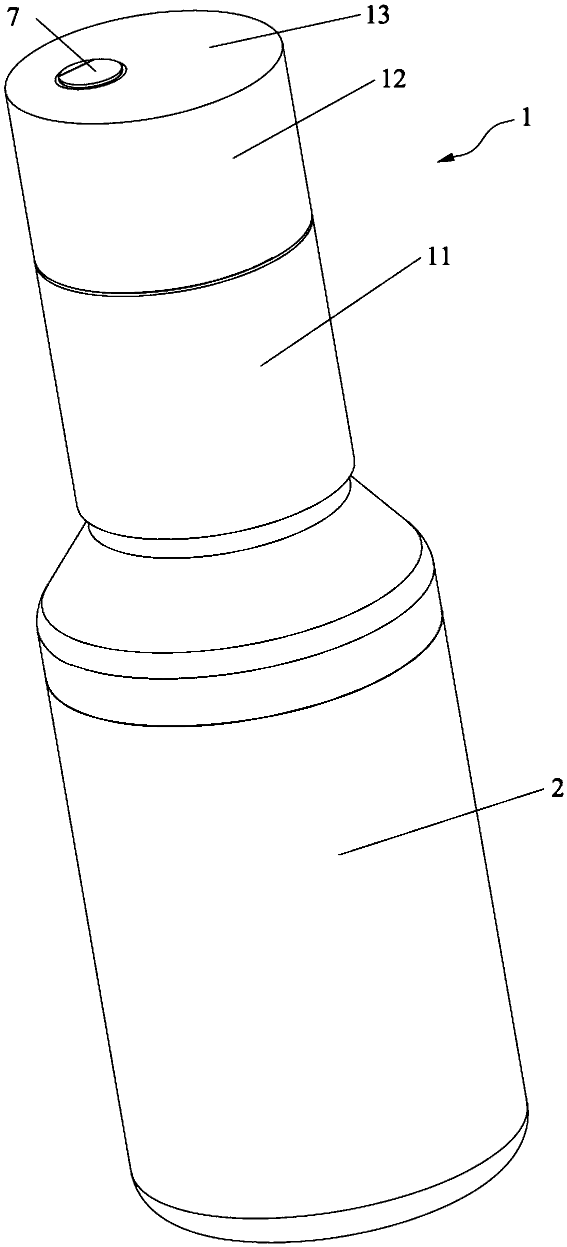
[0045] Such as Figure 1 to Figure 6 As shown, this embodiment discloses a quantitative valve assembly, which includes a bottle cap 1 , an adjustment mechanism, a fixing piece 14 , a first adjustment valve 5 and a second adjustment valve 6 .

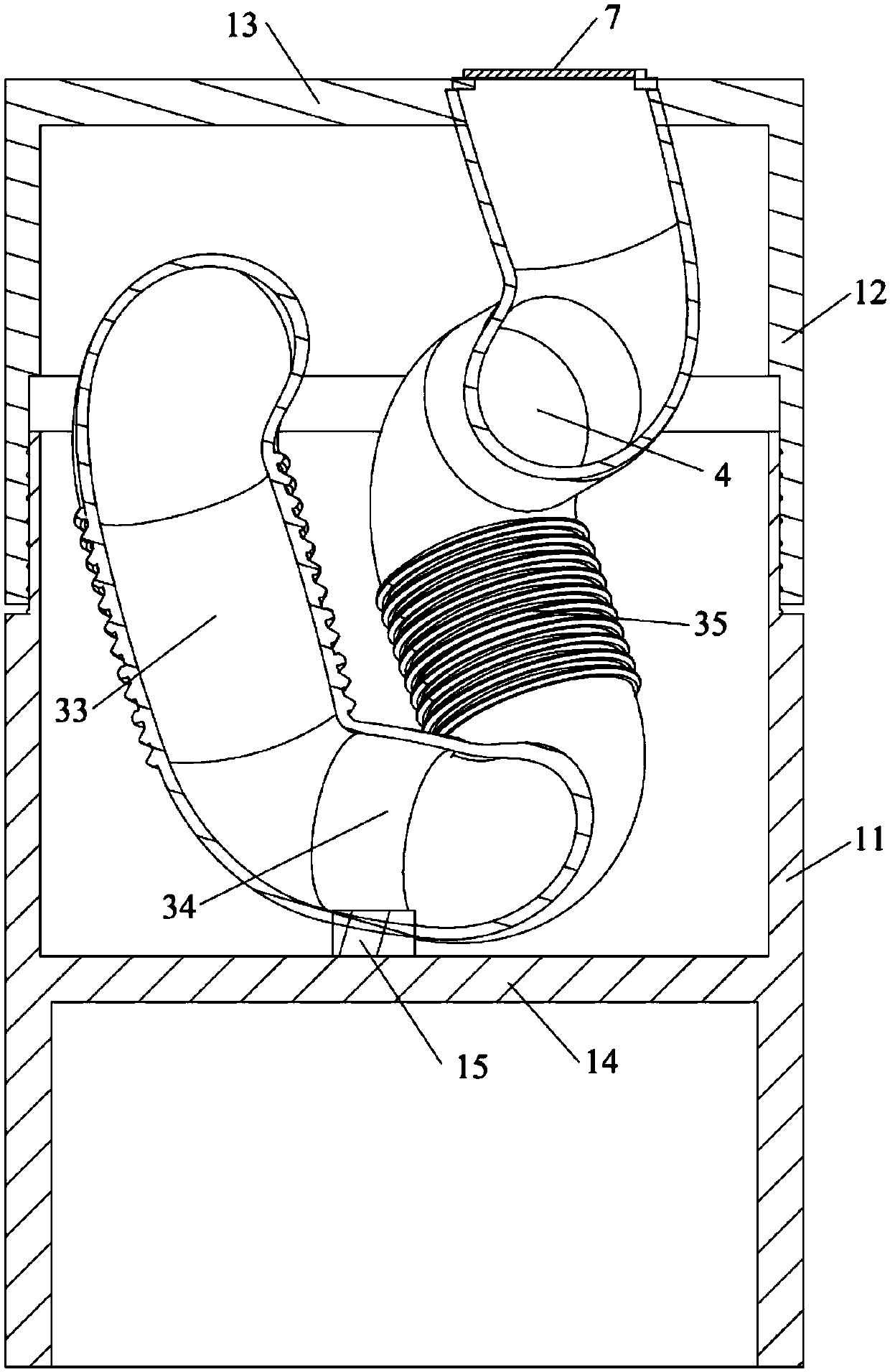
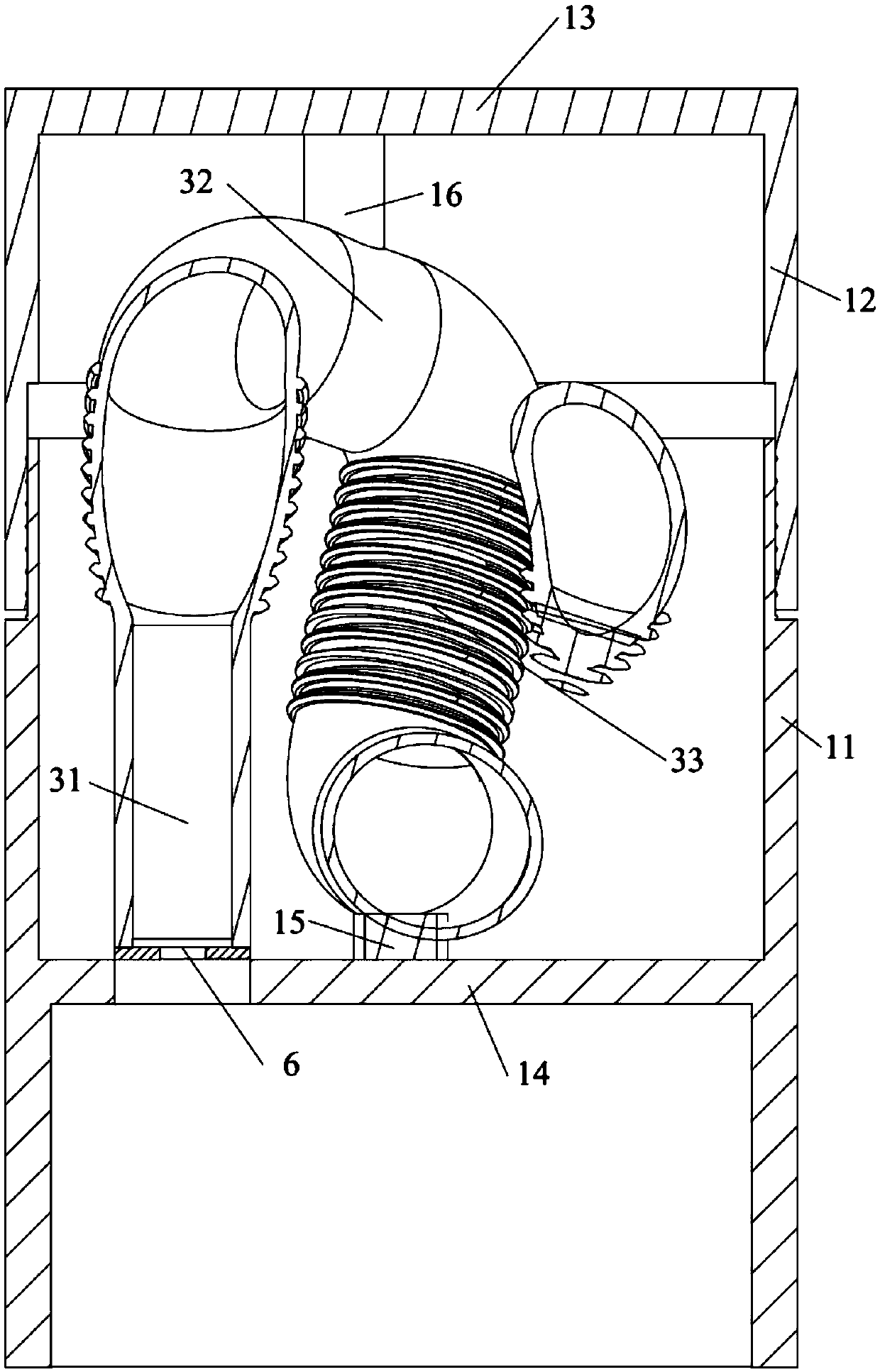
[0046] Among them, such as Figure 2 to Figure 4 As shown, the adjustment mechanism is arranged in the bottle cap 1, and the adjustment mechanism includes a pouring part 4 and a temporary storage part 3 which are sequentially and smoothly connected. The end of the pouring part 4 away from the temporary storage part 3 is fixed on the top cover 13 of the bottle cap 1 and is arranged at the edge of the top cover 13 . A first regulating valve 5 is provided between the pouring part 4 and the temporary storage part 3 , and an end of the temporary storage part 3 away from the pouring part 4 is set toward the opening direction of the bottle cap 1 , and a second regulating valve 6 is provided at this end. When pouring over, the first regulating...

Embodiment 2

[0061] Such as Figure 7 and Figure 8 As shown, this embodiment discloses a quantitative valve assembly. The general structure of the quantitative valve assembly is the same as that in the first embodiment, except that an end cover 17 is provided on the top cover 13, and the on-off valve 7 is not provided. Furthermore, the structure of the adjustment mechanism is different. In this embodiment, a partition 18 is arranged inside the telescopic part 12. The partition 18 includes a vertical part 181 and a horizontal part 182. The first regulating valve 5 is arranged on the horizontal part 182. superior. The vertical part 181 is disposed at the center of the telescopic part 12 , the top end of the vertical part 181 is connected to the top cover 13 , the bottom end is connected to the horizontal part 182 , and the other parts of the horizontal part 182 are connected to the inner sidewall of the telescopic part 12 . The top cover 13 in this embodiment has a semicircular shape, th...


PUM


Abstract

The invention relates to the technical field of quantitative pouring, and discloses a quantitative valve assembly. The assembly comprises a bottle cap, wherein an adjusting mechanism is arranged in the bottle cap, wherein the adjusting mechanism comprises a pouring part and a temporary storage part which are connected in sequence, and one end, away from the temporary storage part, of the pouring-out part is connected to the top cover of the bottle cap, a first regulating valve is arranged between the pouring part and the temporary storage part, far away from the pouring-out part, of the temporary storage part is arranged towards the opening direction of the bottle cap, a second regulating valve is arranged at the end of the first regulating valve, during pouring, the first regulating valvecan be closed, the second adjusting valve can be opened, the liquid can enter the temporary storage portion through the second adjusting valve, the liquid in the inverted-out portion can be poured out, the first regulating valve can be opened, the second regulating valve can be closed, and the liquid in the temporary storage part can partially enter the pouring part. In the vertical process, partof liquid in the temporary storage part can flow into the pouring part, the quantity of the liquid flowing into the pouring-out part at each time is the same, and the quantity of the liquid poured out of the bottle every time can be ensured.

Description

technical field [0001] The invention relates to the technical field of quantitative pouring, in particular to a quantitative valve assembly. Background technique [0002] With the development of social economy, on the basis of satisfying people's material life, they gradually pursue cultural life. In order to increase the sense of life experience, many people have started to learn to cook various delicacies and enjoy them by themselves or with friends. [0003] Liquid condiments such as soy sauce, vinegar, and cooking wine are unavoidably needed in cooking. Liquid condiments are generally contained in bottles, which can be poured out after opening the bottle. [0004] This way of pouring out each time requires the cooking staff to slowly pour out the bottle to control the amount of pouring out. This way is difficult to control the amount of liquid poured out for novices or when shaking hands, and the liquid condiment poured out each time The amount is also different, more...

Claims


Application Information

Patent Timeline
IPC IPC(8): B65D47/04F16K1/18
CPCF16K1/18B65D47/04
Inventor 梁桉滔
Owner 梁桉滔
Why Eureka
Try Eureka