

Novel sleeve isolating and releasing device and using method thereof
A sleeve, a new type of technology, applied in the directions of transportation and packaging, conveyor objects, winding strips, etc., can solve the problems of high economic cost and complicated operation, and achieve improved economic benefits, quick and easy operation, and compact equipment structure. Effect
- Summary
- Abstract
- Description
- Claims
- Application Information
AI Technical Summary
Problems solved by technology
Method used
Image

Examples
Embodiment 1
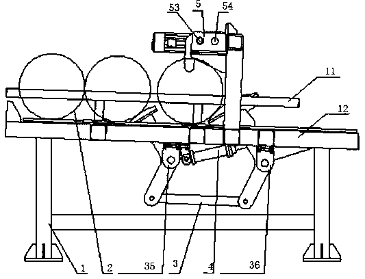
[0057] Such as figure 1 As shown, a new sleeve isolation and release device is composed of a frame 1, four identical sleeves 2, a connecting rod mechanism 3, a power source 4 and a centering mechanism 5.
[0058] The sleeve 2 is placed on the upper surface of the frame 1, the side wall of the sleeve 2 abuts against the upper surface of the frame 1, the upper surface of the frame 1 is an inclined surface, and the sleeve 2 can move along the The upper surface of the frame 1 rolls; the link mechanism 3 is installed on the frame 1; the power source 4 is installed below the frame 1 to drive the movement of the link mechanism 3; the centering mechanism 5 is installed above the frame 1 Location.
[0059] In this embodiment, the upper surface of the frame 1 is an inclined surface, and the sleeve 2 rolls down along the inclined surface of the frame 1 under the action of gravity component force, the forward rolling of the sleeve 2 is blocked by the link mechanism 3, and the power sourc...
Embodiment 2
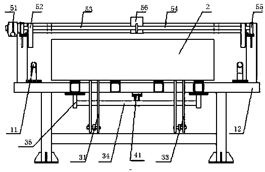
[0062] On the basis of embodiment 1, with reference to figure 1 and figure 2 , The frame 1 is made up of a side rail 11 and a base 12 .
[0063] Side rails 11 are mounted on both sides of the base 12 for preventing the sleeve 2 from rolling out.
Embodiment 3
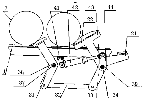
[0065] On the basis of embodiment 1 or 2, with reference to figure 1 and image 3 , The power source 4 is made up of a cylinder base 41, a cylinder 42, a cylinder joint 43 and a swing rod 44.
[0066] The oil cylinder base 41 is installed on the frame 1, and the oil cylinder 42 is installed on the oil cylinder base 41. The oil cylinder 42 is connected with the swing rod 44 through the oil cylinder joint 43, and the swing rod 44 is connected with the link mechanism 3.
[0067] In this embodiment, the movement of the oil cylinder 42 drives the movement of the oil cylinder joint 43 , the movement of the oil cylinder joint 43 drives the movement of the swing rod 44 , and the movement of the swing rod 44 drives the movement of the link mechanism 3 .
PUM
 Abstract
Description
Claims
Application Information