

Vacuum coating equipment and vacuum coating method
A technology of vacuum coating and equipment, applied in vacuum evaporation coating, sputtering coating, ion implantation coating and other directions, can solve the problem of low molecular energy, achieve compact structure, optimize mechanical properties, and improve mechanical properties.
- Summary
- Abstract
- Description
- Claims
- Application Information
AI Technical Summary
Problems solved by technology
Method used
Image

Examples
Embodiment 1
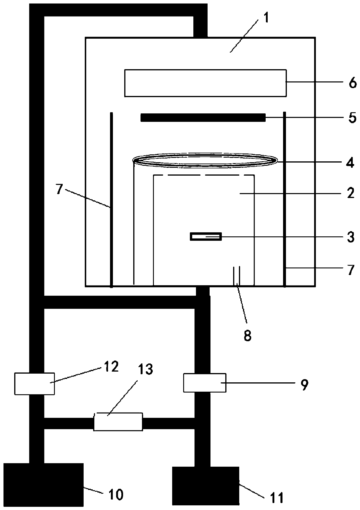
[0043] In this example, if figure 1 As shown, a vacuum coating equipment includes a coating vacuum chamber 1, an evaporation source 3, a sample stage 5, a heating source 6, and an air extraction system. Output heat, and then control the temperature of the sample stage 5 and the substrate arranged on the sample stage 5; a small vacuum chamber 2 communicated with the coating vacuum chamber 1 is also provided, and the nested combination between the coating vacuum chamber 1 and the small vacuum chamber 2 communicates , the small vacuum chamber 2 is arranged inside the coating vacuum chamber 1; the evaporation source 3 is arranged in the small vacuum chamber 2, and the pumping system includes a mechanical pump 10 and a molecular pump 11, and the mechanical pump 10 is respectively connected with the coating vacuum through the rough pumping valve 12. The chamber 1 is connected with the small vacuum chamber 2, and the molecular pump 11 is respectively connected with the coating vacuu...
Embodiment 2
[0077] This embodiment is basically the same as Embodiment 1, especially in that:
[0078] In this embodiment, a vacuum coating method adopts a vacuum coating device of this embodiment, comprising the following steps:
[0079] a. Clean the substrate:
[0080] Use the pre-cleaned silicon wafer or tungsten carbide plate as the substrate, put it into acetone, ethanol, and deionized water for ultrasonic cleaning for 10 minutes each, and then dry it with nitrogen;
[0081] b. Place the substrate:
[0082] The cleaned substrate is placed and transferred to the coating vacuum chamber 1, and placed on the sample stage 5, and the sample stage 5 is connected to the negative bias power supply;
[0083] c. Load preparation materials:
[0084] Transfer the cleaned sample to the small vacuum chamber 2, put the fullerene powder into the evaporation boat, fix it, and then put it into the small vacuum chamber 2 together;
[0085] d. Vacuum coating:
[0086] Turn on the exhaust system, eva...
Embodiment 3
[0091] This embodiment is basically the same as the previous embodiment, and the special features are:
[0092] In this embodiment, a vacuum coating method adopts a vacuum coating device of this embodiment, comprising the following steps:
[0093] a. Clean the substrate:
[0094] The pre-cleaned sapphire substrate was used as the substrate, ultrasonically cleaned in acetone, ethanol, and deionized water for 10 minutes each, and then dried with nitrogen;
[0095] b. Place the substrate:
[0096] The cleaned substrate is placed and transferred to the coating vacuum chamber 1, and placed on the sample stage 5, and the sample stage 5 is connected to the negative bias power supply;
[0097] c. Load preparation materials:
[0098] Transfer the cleaned sample to the small vacuum chamber 2, put the fullerene powder into the evaporation boat, fix it, and then put it into the small vacuum chamber 2 together;
[0099] d. Vacuum coating:
[0100] Turn on the exhaust system, evacuate ...
PUM
| Property | Measurement | Unit |
|---|---|---|
| Resistivity | aaaaa | aaaaa |
| Hardness | aaaaa | aaaaa |
| Hardness | aaaaa | aaaaa |
Abstract
Description
Claims
Application Information