Quenching and tempering system for oil-containing sludge

A sludge conditioning and conditioning technology, applied in sludge treatment, water/sludge/sewage treatment, mixers, etc., can solve the problems of complex causes and difficult treatment, and achieve sufficient conditioning and good conditioning effect. , effects that are easy to re-refine and exploit

Active Publication Date: 2019-04-19
北京净界新宇环保科技有限公司
View PDF5 Cites 1 Cited by
  • Summary
  • Abstract
  • Description
  • Claims
  • Application Information

AI Technical Summary

Problems solved by technology

[0004] The properties of oil sludge are various, there are many types, and the causes are complicated. Moreover, oil sludge is mostly a mixture of water, mud, oil and other impurities, and it is difficult to deal with.
For different types of oil sludge, the treatment technologies and processes are also corresponding, and there are various methods. Each method has its advantages, disadvantages and scope of application; but there is no one treatment method that can be economical, efficient, and can handle all types of oil sludge. Purpose, the existing conditioning device can no longer control the viscosity of sludge in the process of conditioning; with the increasingly stringent and perfect environmental protection regulations, and the increasing shortage of oil resources, the reduction of sludge, harmless Recycling, recycling, and clean treatment technologies will become an inevitable trend of its development

Method used


Image

  • Quenching and tempering system for oil-containing sludge
  • Quenching and tempering system for oil-containing sludge
  • Quenching and tempering system for oil-containing sludge

Examples


Embodiment 1

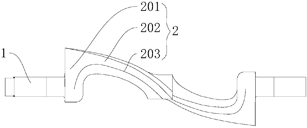
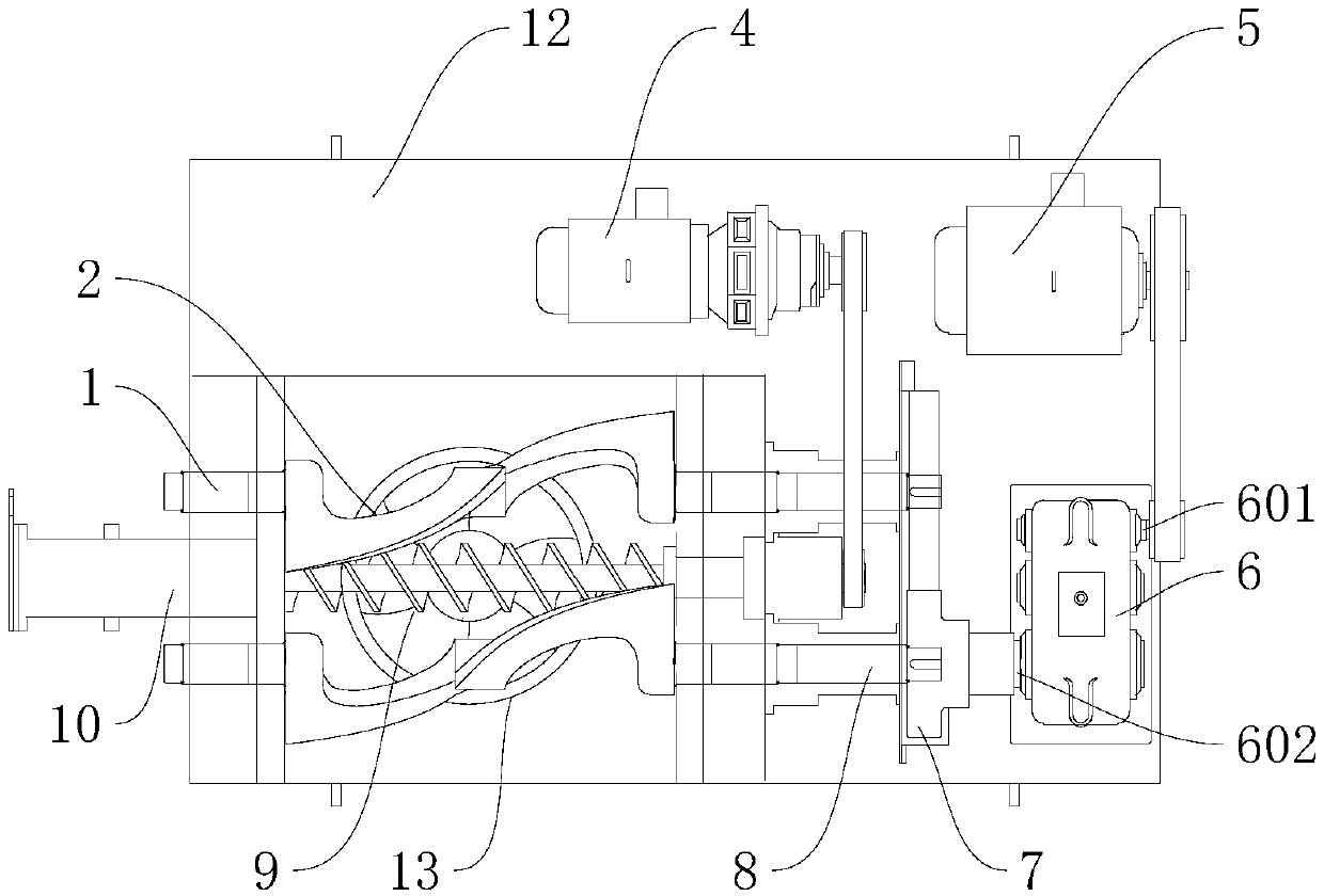
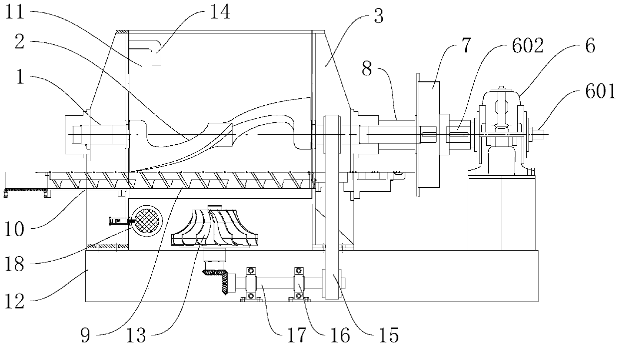
[0038] Such as figure 1 , figure 2 , image 3 As shown, this embodiment discloses a conditioning system for oily sludge, which includes a main body 3 on which a conditioning chamber 11 and a conditioning device are arranged. Specifically, the tempering device includes two tempering blades located in the tempering bin 11 of the main body 3 and turning in opposite directions. The tempering blades include two tempering parts symmetrically arranged in the center. The quality part includes a rotating shaft part 1 and a stirring part 2 connected to each other, and the stirring parts 2 of the two conditioning parts are connected to each other and the rotating shaft part 1 is arranged coaxially.

[0039] A viscosity detection device 18 is arranged in the tempering bin, and the viscosity detection device 18 includes a housing 181 fixed on the main body 3, a detection chamber is arranged in the housing, and a detection assembly is arranged in the detection chamber ; One end of the h...

Embodiment 2

[0043] This embodiment discloses a conditioning system for oily sludge. The same as in Example 1, the conditioning system disclosed in this embodiment includes a main body 3 on which a conditioning chamber 11 and a conditioning device are arranged. Specifically, the tempering device includes two tempering blades located in the tempering bin 11 of the main body 3 and turning in opposite directions. The tempering blades include two tempering parts symmetrically arranged in the center. The quality part includes a rotating shaft part 1 and a stirring part 2 connected to each other, and the stirring parts 2 of the two conditioning parts are connected to each other and the rotating shaft part 1 is arranged coaxially.

[0044] Such as Figure 5 As shown, the viscosity detection device 18 is arranged in the tempering chamber, and the viscosity detection device 18 includes a housing 181 fixed on the main body 3, a detection chamber is arranged in the housing, and a detection chamber is...

Embodiment 3

[0050] This embodiment discloses a conditioning system for oily sludge. The same as in Example 1, the conditioning system disclosed in this embodiment includes a main body 3 on which a conditioning chamber 11 and a conditioning device are arranged. Specifically, the tempering device includes two tempering blades located in the tempering bin 11 of the main body 3 and turning in opposite directions. The tempering blades include two tempering parts symmetrically arranged in the center. The quality part includes a rotating shaft part 1 and a stirring part 2 connected to each other, and the stirring parts 2 of the two conditioning parts are connected to each other and the rotating shaft part 1 is arranged coaxially.

[0051] A viscosity detection device 18 is arranged in the tempering bin, and the viscosity detection device 18 includes a housing 181 fixed on the main body 3, a detection chamber is arranged in the housing, and a detection assembly is arranged in the detection chamber...


PUM


Abstract

The invention relates to the technical field of oil-containing sludge treatment, in particular to a quenching and tempering system for oil-containing sludge. The system comprises a body, the body is provided with a quenching and tempering chamber and a quenching and tempering device. The quenching and tempering device comprises two quenching and tempering blades which are located in the quenchingand tempering chamber of the body with opposite rotation directions, the quenching and tempering blades comprise two quenching and tempering parts which are symmetrically arranged, the quenching and tempering parts comprise rotary members and stirring members which are mutually connected, and the stirring parts of the two quenching and tempering parts are mutually connected and coaxial with the rotary members; the quenching and tempering chamber is internally provided with a viscosity level detecting device, the body is provided with a water inlet device, and the starting and stopping of the water inlet device are controlled by the viscosity level detecting device. According to the quenching and tempering system, a quenching and tempering agent is added to the quenching and tempering chamber when quenching and tempering are conducted, oil-containing sludge is fully quenched and tempered by the rotation of the two quenching and tempering blades; by arranging multiple quenching and tempering blades which achieve quenching and tempering by rotating in different directions, the quenching and tempering is thorougher, the quenching and tempering effect is better, deep reduction of oil-containing sludge quenching and tempering is achieved; the refining and using of resources can be achieved by quenched and tempered oil-containing sludge more easily.

Description

technical field [0001] The invention relates to the technical field of oily sludge treatment, and relates to a treatment equipment that can be used for oily sludge conditioning and tempering, in particular to an oily sludge conditioning system. Background technique [0002] Due to the rapid development of the world economy, the demand for oil is increasing. The oil field needs to drill many oil wells every year, and the refinery is also constantly expanding and increasing the load; in the process of oil exploration, extraction, refining, tank cleaning, storage and transportation, Due to accidents, leakage, natural settlement and other reasons, a large amount of crude oil or oil products and soil, water or other impurities form oily sludge or sewage; oily sludge or oily sewage contains petroleum, water and inorganic solids, etc. Hazardous pollutants that can cause great harm to the environment. [0003] At present, there are some mature technologies and methods in oil sludge...

Claims


Application Information

Patent Timeline
Patent Type & Authority Applications(China)
IPC IPC(8): C02F11/00B01F7/02B01F15/00
CPCC02F11/00B01F27/11B01F27/172B01F27/60B01F35/2136
Inventor 秦凯宁红创孔维轩
Owner 北京净界新宇环保科技有限公司
Why Eureka
Try Eureka