Prefabricated underground diaphragm wall and its construction method

An underground diaphragm wall, prefabricated technology, applied in sheet pile walls, infrastructure engineering, construction, etc., can solve the problems of uplift of diaphragm wall components and reduce the overall performance of the diaphragm wall, so as to reduce the phenomenon of uplift or depression and improve construction. Efficiency, the effect of reducing the possibility of position shift

Active Publication Date: 2021-02-26
江苏城归设计有限公司
View PDF1 Cites 0 Cited by
  • Summary
  • Abstract
  • Description
  • Claims
  • Application Information

AI Technical Summary

Problems solved by technology

[0004] During the construction of this prefabricated underground diaphragm wall, two adjacent diaphragm wall members are attached to each other. When the surrounding temperature is high or low, the diaphragm wall members will expand with heat and contract with cold. There will be a gap between two adjacent diaphragm wall components. When the heat expands, the diaphragm wall members will have a heaving phenomenon. Whether it is a depression or a heave phenomenon, the overall performance of the underground diaphragm wall will be reduced.

Method used


Image

  • Prefabricated underground diaphragm wall and its construction method
  • Prefabricated underground diaphragm wall and its construction method
  • Prefabricated underground diaphragm wall and its construction method

Examples


Embodiment 1

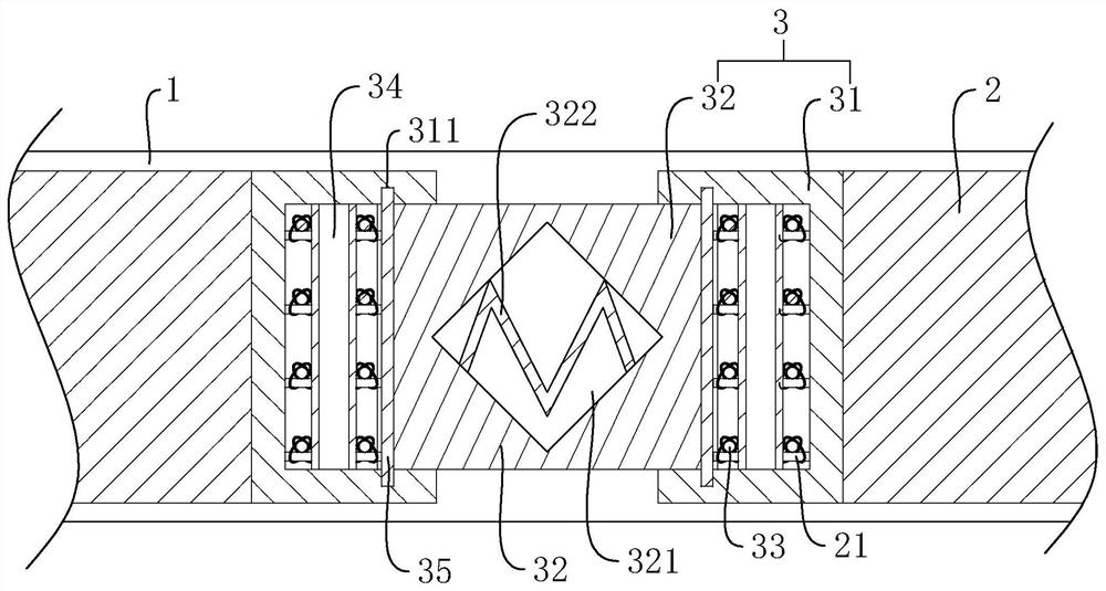
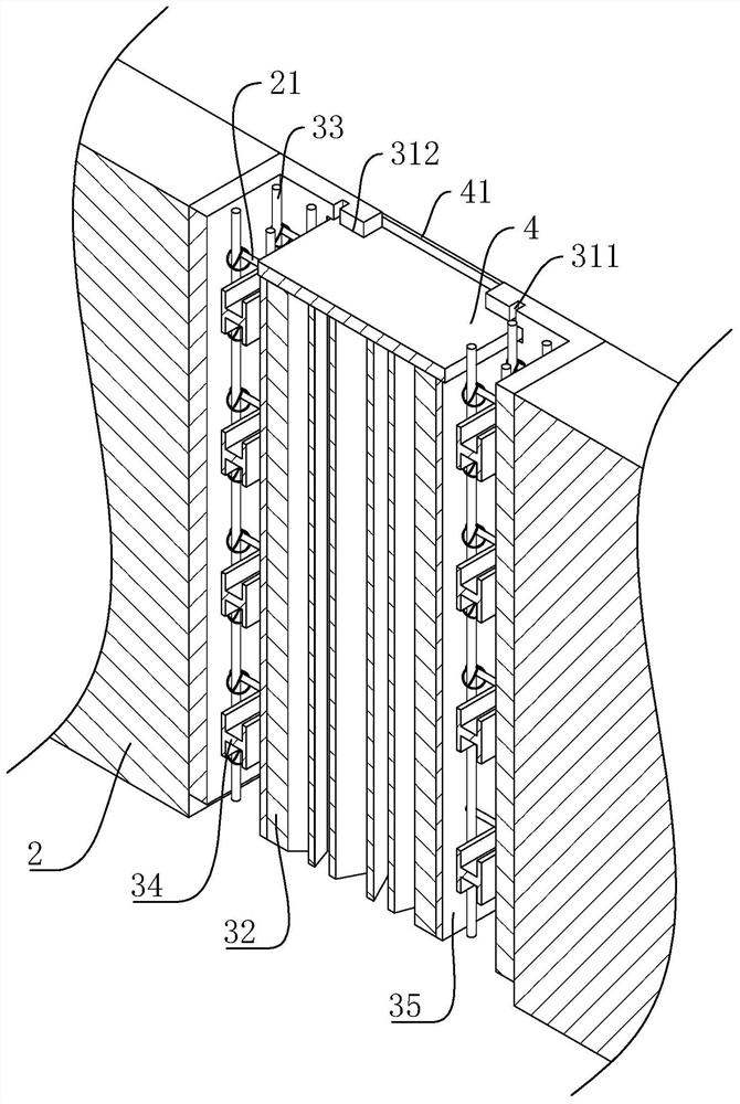
[0042] Embodiment 1: A kind of prefabricated underground diaphragm wall, refer to figure 1 , including the installation channel 1 opened on the ground, several continuous wall units 2 are placed in sequence in the installation channel 1, and a telescopic assembly 3 is sandwiched between two adjacent continuous wall units 2. The telescopic assembly 3 includes two installation Plate 31 and a telescopic rubber strip 32, two mounting plates 31 are attached to the opposite side walls of adjacent continuous wall units 2. The stretchable rubber strip 32 has elastic force and can produce corresponding changes according to the change of the gap between two adjacent continuous wall units 2 , so that the space between two adjacent continuous wall units 2 is always kept in a filled state.

[0043] refer to figure 1 , the transverse cross-sectional view of the mounting plate 31 is "U" shape, the opening of the mounting plate 31 faces the telescopic rubber strip 32, and the telescopic rubb...

Embodiment 2

[0048] Embodiment 2: a kind of construction method that is used for prefabricated underground diaphragm wall, its specific steps are as follows:

[0049] S1. Use an excavator to excavate and install the canal 1, and the side wall of the installation canal 1 is supported by supporting steel bars. When excavating, it should be ensured that the side wall of the installation channel 1 is vertical and the bottom is horizontal;

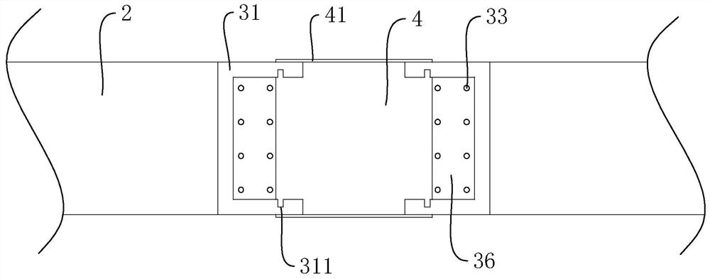
[0050] S2. Before hoisting the continuous wall unit 2, attach the installation plate 31 to the continuous wall unit 2. During the installation process, the reinforcement anchor bar 21 should pass through the installation plate 31, and then vertically place a strong steel bar 33 inside the installation plate 31 , the joint between the strong steel bar 33 and the reinforcement anchor bar 21 is wound and tightened by steel wire;

[0051] S3, after the installation of the reinforced anchor bar 21 and the strong steel bar 33 is completed, place the support stee...


PUM


Abstract

The present invention relates to the technical field of civil engineering, and aims to provide a prefabricated underground diaphragm wall and its construction method. The key point of the technical solution is to set up an installation channel on the ground, and several diaphragm wall units are sequentially placed in the installation channel , a telescopic assembly is sandwiched between two adjacent continuous wall units. The telescopic assembly includes two mounting plates and a telescopic rubber strip. The telescopic rubber strip is sandwiched between two mounting plates. The panels are attached to the opposite side walls of the two continuous wall units respectively. In the present invention, the telescopic rubber strips can adapt to the effect of thermal expansion and contraction between the continuous wall units, thereby reducing the possibility of bulge or depression between the continuous wall units.

Description

technical field [0001] The invention relates to the technical field of civil engineering, in particular to an assembled underground diaphragm wall and a construction method thereof. Background technique [0002] Diaphragm wall is the preferred structural form for deep foundation construction and deep foundation pit enclosure, and has been widely used all over the world. At present, the underground diaphragm wall is replacing many traditional deep foundations and deep foundation pit enclosure structures and construction methods. The underground diaphragm wall has little vibration and low noise during construction, and is suitable for construction in densely built urban areas; the wall has high rigidity and good anti-seepage performance; it can be applied to various geological conditions. The underground diaphragm wall can make full use of the limited ground and space within the red line of the building, and give full play to the investment benefits; it has high work efficien...

Claims


Application Information

Patent Timeline
Patent Type & Authority Patents(China)
IPC IPC(8): E02D5/18E02D5/20
CPCE02D5/185E02D5/20
Inventor 石云
Owner 江苏城归设计有限公司
Why Eureka
Try Eureka