Medical gas manifold control system and gas switching control method thereof

A gas busbar and gas switching technology, which is applied in the field of busbars, can solve the problems of inconvenient management, increased production costs, complicated operation steps, etc., and achieves the effects of simple operation and maintenance, increased service life, and remote control.

Active Publication Date: 2020-05-22
珠海奥吉赛医疗科技股份有限公司
View PDF6 Cites 0 Cited by
  • Summary
  • Abstract
  • Description
  • Claims
  • Application Information

AI Technical Summary

Problems solved by technology

[0003] At present, the structures of the medical gas manifold devices used are generally the same. Most of them are assembled or welded by tees, small stop valves, and pipe sections, and then a large stop valve and a pressure reducer are installed at the outlet. Pipes connecting gas cylinders; moreover, dual circuits are often used to supply medical gas. When the medical gas in one circuit is used up and needs to be switched to another circuit for supply, manual or solenoid valve switching is basically used, which is inconvenient to use manual switching Management, using electromagnetic valve switching, the operation steps are complicated, which affects the rescue time, and it will not work normally in case of power failure
[0004] At the same time, in the existing medical gas bus system, the whole system consists of a large number of components, large volume, heavy weight, high cost, time-consuming and laborious assembly, which greatly increases the production cost; In addition to manually opening the valve on the gas cylinder, you have to manually open the small shut-off valve in the system; on the contrary, when changing the gas cylinder, in addition to manually closing the valve on the gas cylinder, you have to manually close the small shut-off valve, so as not to cause damage to the system. Gas leakage; however, the centralized gas supply bus is generally only connected to several steel cylinders, which makes the whole system complex and greatly increases the possibility of gas leakage
In addition, when the small and medium shut-off valves in the system are damaged and need to be repaired, the system must be completely disassembled before replacement, making maintenance difficult

Method used


Image

  • Medical gas manifold control system and gas switching control method thereof
  • Medical gas manifold control system and gas switching control method thereof
  • Medical gas manifold control system and gas switching control method thereof

Examples


Embodiment Construction

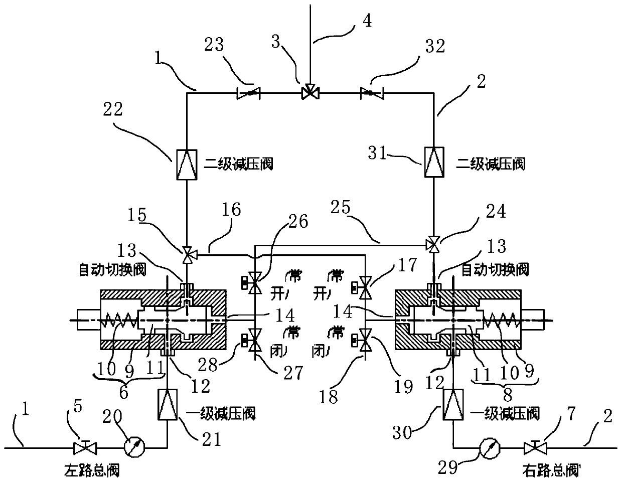
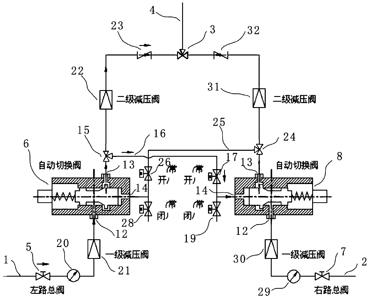
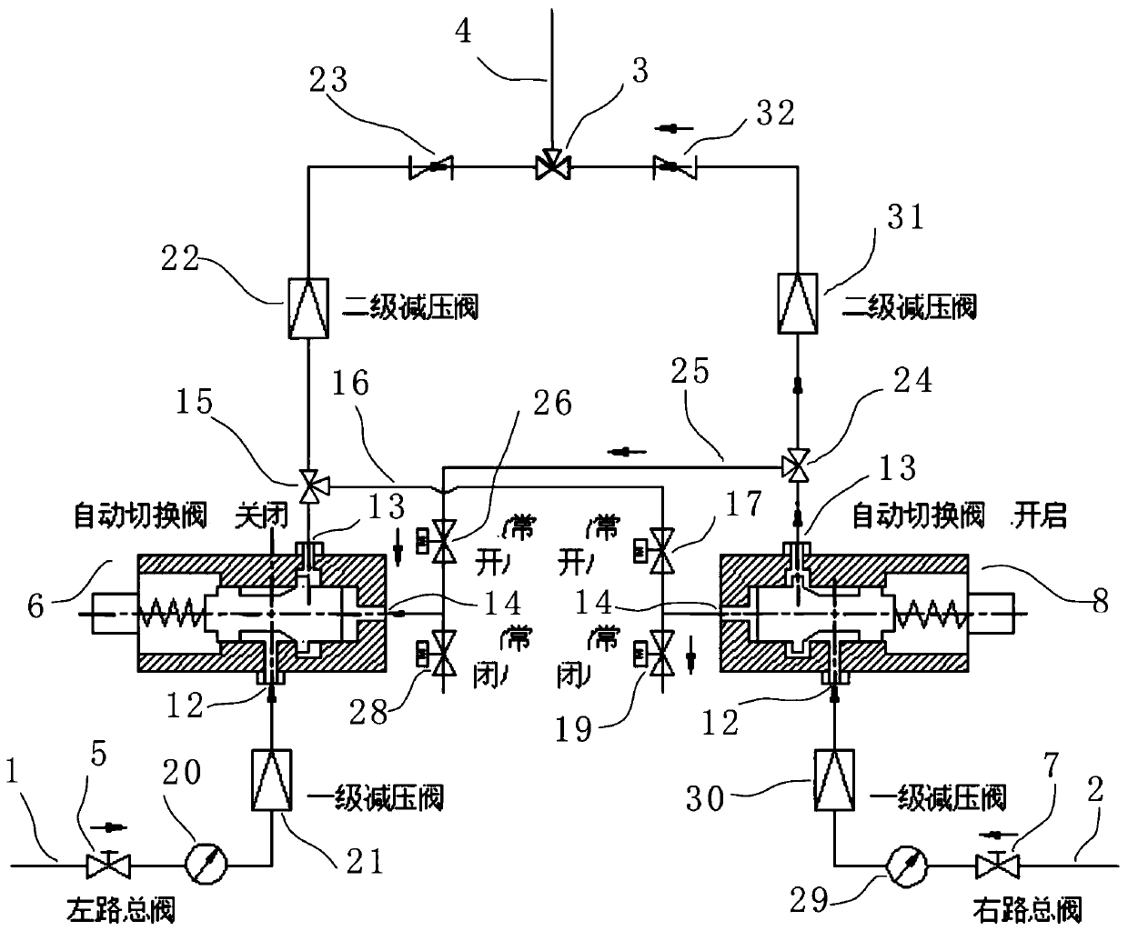
[0041] The medical gas manifold control system is mainly used in the medical gas pipeline with the left and right gas cylinders, such as figure 1 As shown, it includes a left trachea branch 1, a right trachea branch 2, a first three-way valve 3 and a confluence outlet pipeline 4. The left trachea branch 1 is provided with a left main valve 5 for controlling the on-off of the gas circuit. The left air pipe branch 1 on the rear side of the left main valve 5 is connected with a left automatic gas switching valve 6 which adopts pipeline gas for automatic control and is connected by a three-way connection; Road main valve 7, the right air pipe branch 2 on the rear side of the right main valve 7 is connected with the right automatic gas switching valve 8 that adopts pipeline gas for automatic control and three-way connection; the output pipeline of the left automatic gas switching valve 6 and the output pipeline of the right automatic gas switching valve 8 are respectively connected...


PUM


Abstract

The invention provides a medical gas busbar control system. The medical gas busbar control system comprises a left gas pipe branch pipe, a right gas pipe branch pipe, a first three-way valve and a convergence gas outlet pipe. A left main valve is arranged on the left gas pipe branch pipe. A left automatic gas switching valve is connected to the position, on the rear side of the left main valve, ofthe left gas pipe branch pipe. A right main valve is arranged on the right gas pipe branch pipe. A right automatic gas switching valve is connected to the position, on the rear side of the right mainvalve, of the right gas pipe branch pipe. An output pipe of the left automatic gas switching valve and an output pipe of the right automatic gas switching valve are connected with the convergence gasoutlet pipe through the first three-way valve. The left gas pipe branch pipe and the right gas pipe branch pipe are automatically switched through the left automatic gas switching valve and the rightautomatic gas switching valve. The medical gas busbar control system realizes automatic switching between the left gas pipe branch pipe and the right gas pipe branch pipe, conducts automatic switching control according to the remaining gas pressure value, implements automatic switching to exchange gas after power-off and maintains pressure stability after gas exchange. The invention further provides a gas switching control method of the medical gas busbar control system.

Description

【Technical field】 [0001] The invention relates to busbar technology, in particular to a medical gas busbar control system and a gas switching control method thereof. 【Background technique】 [0002] The gas manifold is the main component of the centralized gas supply equipment. It gathers the gas sources of a single gas supply at a single gas point, and collects the same gas in several gas cylinders into the same pipeline. Pipelines transport gas to various workplaces. It is generally installed in an independent building or adjacent to a factory building. The use of busbars can save the number of cylinder changes, reduce labor intensity and save labor costs, and allow centralized management of high-pressure gas, which can reduce the existence of safety hazards and save site space. Good and reasonable use of site space is convenient for gas management. The gas manifold is suitable for enterprises with large gas consumption. The principle is to input bottled gas to the main pi...

Claims


Application Information

Patent Timeline
Patent Type & Authority Patents(China)
IPC IPC(8): F17D1/02F17D3/01F17C7/00F17C13/00F17C13/02F17C13/04
CPCF17C7/00F17C13/00F17C13/025F17C13/045F17C2223/0123F17C2225/0123F17C2270/02F17D1/02F17D3/01
Inventor 李世强郭荣春杨冠林周军
Owner 珠海奥吉赛医疗科技股份有限公司
Why Eureka
Try Eureka