Storage tank
A technology for storage and adjustment of space, applied in the field of storage, which can solve problems such as easy drying
- Summary
- Abstract
- Description
- Claims
- Application Information
AI Technical Summary
Problems solved by technology
Method used
Image

Examples
no. 1 Embodiment approach
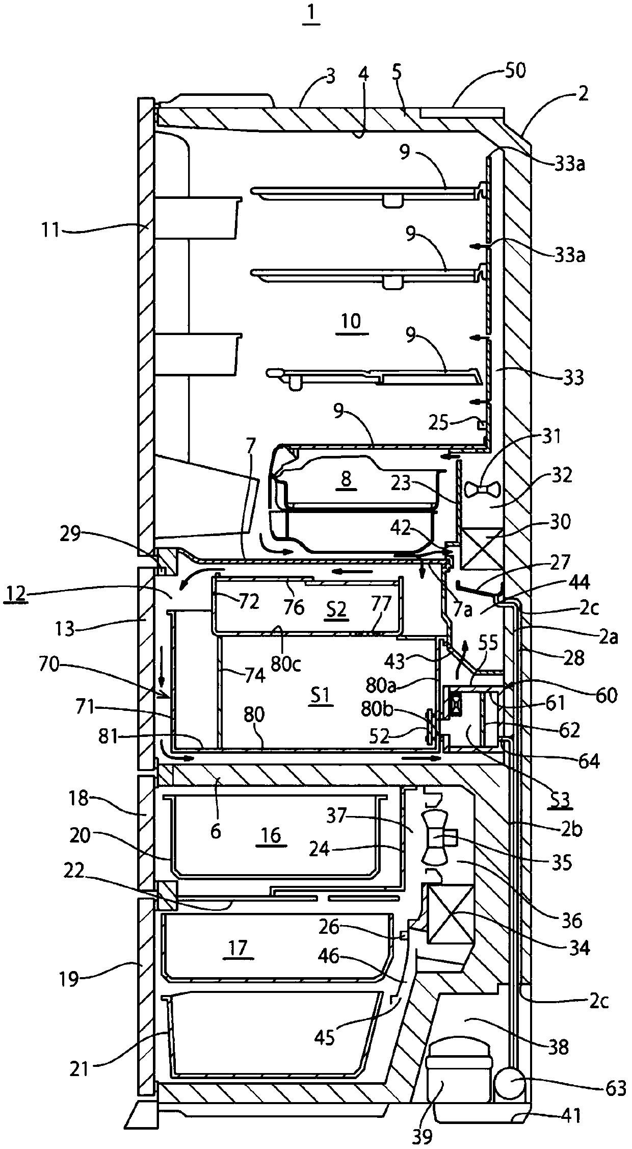
[0020] Next, the storage of the first embodiment will be described with reference to the drawings. In the present embodiment, a refrigerator 1 in which a storage space installed inside is cooled to a predetermined temperature is described as a storage, but the present invention can also be used in a food storage without a cooling function.
[0021] like figure 1 As shown, the refrigerator 1 according to this embodiment includes a cabinet 2 formed of a heat-insulating box opened at the front. The cabinet body 2 has heat insulating materials such as vacuum heat insulating material and foam heat insulating material in the heat insulating space 5 formed between the outer box 3 made of steel plate and the inner box 4 made of synthetic resin. The cabinet body 2 is provided with a plurality of storage spaces inside the inner box 4, and the storage spaces are divided up and down by a heat-insulating partition wall 6 .
[0022] The space above the insulating partition wall 6 is a sto...
no. 2 Embodiment approach
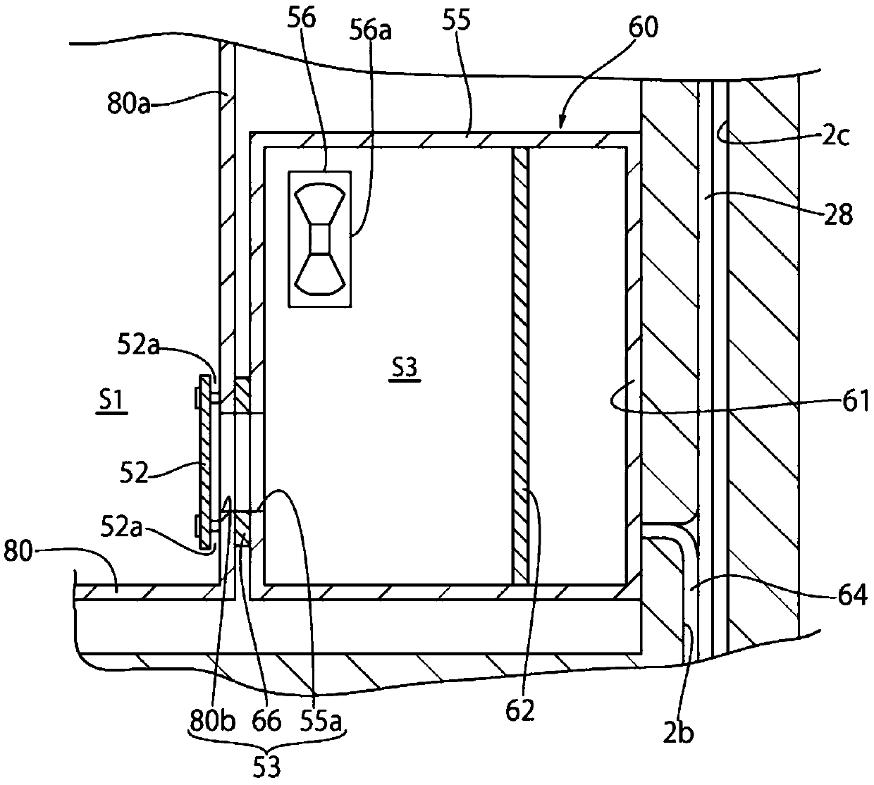
[0070] refer to image 3 A second embodiment will be described. In addition, the same code|symbol is attached|subjected to the same structure as 1st Embodiment, and the description of the structure is abbreviate|omitted.
[0071] In the above-mentioned first embodiment, the case where a plate-shaped member is provided as the wind restricting part 52 to cover the opening 80 b with a gap 52 a between the rear wall 80 a of the lower rear container 80 has been described. The shutter 152 that closes the opening 55a of the adjustment container 55 and switches the flow of wind in the communicating portion 53 and releases it serves as a wind restricting portion.
[0072] In this embodiment, through the image 3 As shown, when performing reduced-oxygen operation, the opening 55a of the adjustment container 55 is reduced by the shutter 152. Even if the air in the adjustment space S3 is stirred by the stirring fan 56, it is difficult for the air in the adjustment space S3 to pass throu...
no. 3 Embodiment approach
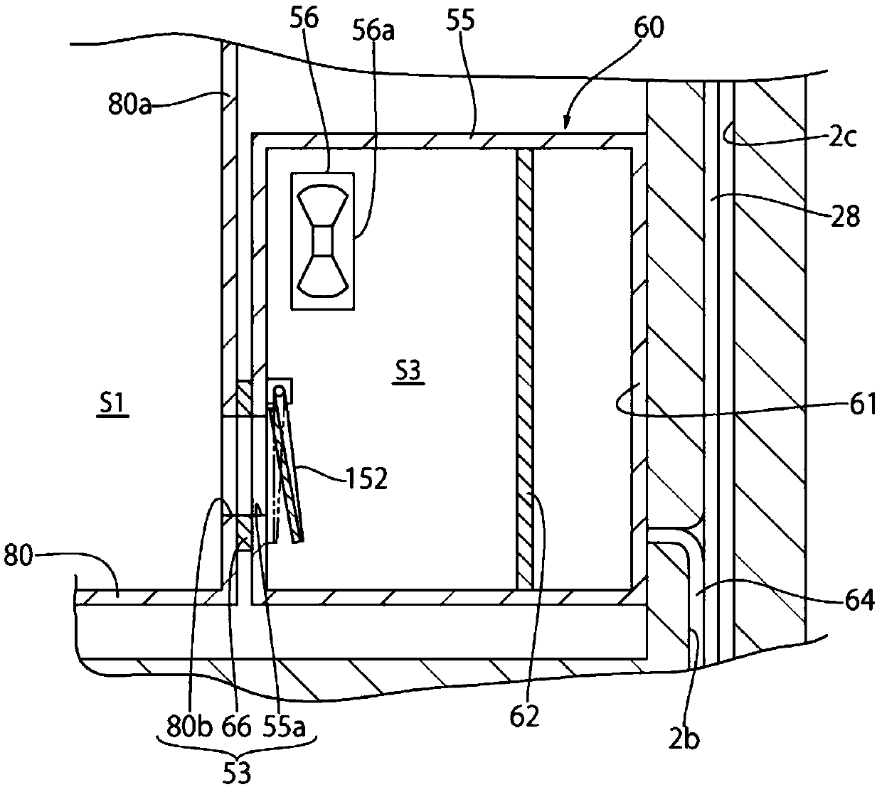
[0076] refer to Figure 4 A third embodiment will be described. In addition, the same code|symbol is attached|subjected to the same structure as 1st Embodiment, and the description of the structure is abbreviate|omitted.
[0077] The above-mentioned first embodiment has described the case where a plate-shaped member is provided as the wind restricting portion 52 to cover the opening 80 b with the gap 52 a between the rear wall 80 a of the lower rear container 80 , but in this embodiment, a plugging adjustment container is provided. The air-permeable sheet 252 provided in the opening 55a of 55 serves as a wind restricting part.
[0078] The air-permeable sheet 252 is a waterproof and moisture-permeable plate, such as a porous sheet with a plurality of holes with a diameter of 0.5 μm to 3 μm, allowing water vapor particles and oxygen molecules to pass through, but blocking water particles larger than the pores. In addition, since the air-permeable sheet 252 is porous, the air ...
PUM
 Abstract
Description
Claims
Application Information
 - R&D Engineer
- R&D Manager
- IP Professional
- Industry Leading Data Capabilities
- Powerful AI technology
- Patent DNA Extraction
Browse by: Latest US Patents, China's latest patents, Technical Efficacy Thesaurus, Application Domain, Technology Topic.
© 2024 PatSnap. All rights reserved.Legal|Privacy policy|Modern Slavery Act Transparency Statement|Sitemap