Method for traveling wave phase control between conformal waveguide slot array antenna radiation arrays

A phase control, array antenna technology, applied to antenna arrays, individually powered antenna arrays, antennas, etc., can solve problems such as being unsuitable for engineering applications and narrow bandwidth, and achieve the effects of being suitable for engineering applications, flexible in design, and improving radiation performance

Inactive Publication Date: 2019-04-19
10TH RES INST OF CETC
View PDF5 Cites 6 Cited by
  • Summary
  • Abstract
  • Description
  • Claims
  • Application Information

AI Technical Summary

Problems solved by technology

However, the above-mentioned end-feed method has obvious disadvantages: the bandwidth is very narrow, the longer the radiation line array, the more the number of radiation slots on the radiation line array, the narrower the bandwidth, because the bandwidth of the slot array is related to the number of slots on each line array Inversely proportional
However, it is obviously difficult to expand the bandwidth of the cylindrical conformal slot array based on the end-feed principle to compensate the spatial phase difference by dividing the sub-array, which limits the performance improvement of the antenna and is not suitable for engineering applications.

Method used


Image

  • Method for traveling wave phase control between conformal waveguide slot array antenna radiation arrays

Examples


Embodiment Construction

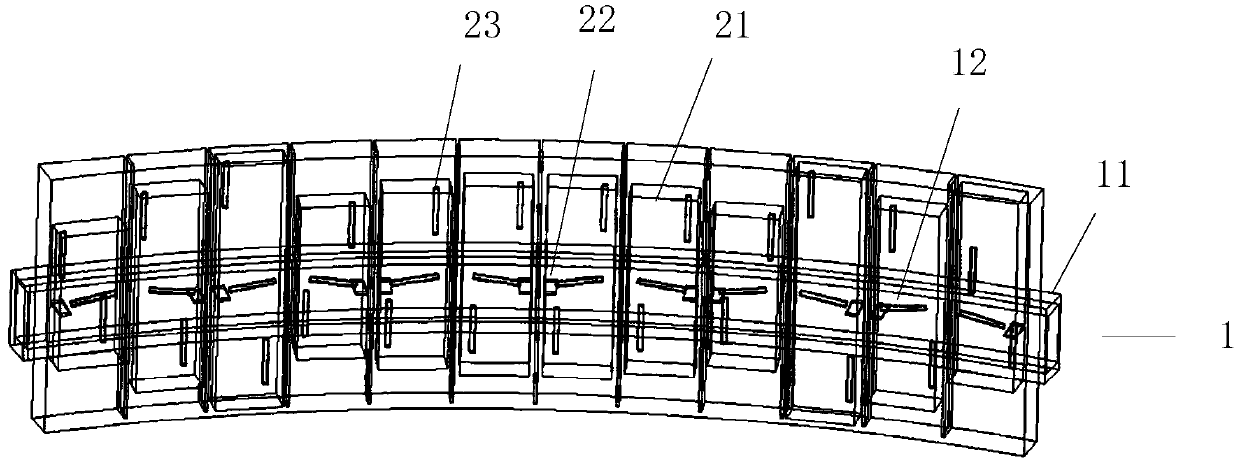
[0015] refer to figure 1 . The cylindrical conformal slot array antenna is composed of a radiation layer and a coupling layer. The coupling layer is an arc-shaped waveguide, which feeds power to the radiation array through the coupling slots on its common wall. According to the need to expand the bandwidth, the radiation line array in the cylindrical conformal waveguide slot array is divided into any number of radiation sub-arrays, and a thin film with the same thickness as the waveguide is added above the coupling slot in the central area of ​​each radiation sub-array waveguide. It is used to compensate the spatial phase error caused by the conformal shape of the cylindrical surface; the coupling slot is used to feed power from the center of each radiating line array sub-array, and the traveling wave power of the waveguide slots at both ends of each radiating sub-array is controlled. The desired phase is controlled by the distance between the longitudinal slot and the coupli...


PUM


Abstract

The method for traveling wave phase control between conformal waveguide slot array antenna radiation arrays disclosed in the present invention aims to provide a feed phase method for controlling the radiation arrays in the conformal waveguide slot arrays capable of improving an antenna pattern and being more suitable for engineering application. The implementation method comprises the following steps of: according to the need of expanding the bandwidth, dividing a radiation array in the conformal waveguide slot array into a plurality of any radiation sub arrays, employing coupling slits to perform feed from the center of each radiation array sub array, adding thin film pieces with the same thickness as the waveguides at the upper portions of the coupling slits of the center region of eachradiation sub array waveguide, and controlling the waveguide slit travelling power of two ends of each radiation sub array. The distance of diaphragm deviated from the centers of the sub arrays and the width of the diaphragm are regulated to achieve the matching of the power distribution and the traveling waves. the phase compensation scheme is flexible in design, and is very suitable for engineering application. The method for traveling wave phase control between conformal waveguide slot array antenna radiation arrays is specially suitable for cylindrical conformal waveguide slot array antennas for compensating for spatial phase errors caused by cylindrical conformation.

Description

technical field [0001] The invention relates to the field of waveguide slot array antennas, in particular to a method for controlling the phase of traveling waves between radiation arrays of waveguide cylinder conformal slot array antennas. technical background [0002] The slot array antenna is usually a planar array, including a coupling array and a radiation array. The energy is coupled to the radiation array through the coupling array, and the energy is radiated out through the radiation slot. Both the coupling array and the radiation array adopt a resonant design to ensure that each radiation slot In-phase requirements. More and more requirements require the antenna to conform to the platform carrier, which puts forward higher requirements for the slot array antenna. The cylindrical conformal slot array antenna requires the antenna to be conformal to the cylindrical surface, so that the multiple radiation arrays constituting the radiation array are arranged along the c...

Claims


Application Information

Patent Timeline
IPC IPC(8): H01Q3/34H01Q21/06H01Q21/00
CPCH01Q3/34H01Q21/0006H01Q21/0018H01Q21/061
Inventor 李秀梅刘熠志张云何海丹
Owner 10TH RES INST OF CETC
Why Eureka
Try Eureka