
Electrical connector

A technology of electrical connectors and connecting bridges, which is applied in the direction of connection, fixed connection, clamping/spring connection, etc., can solve the problems of power connector reliability reduction, etc., and achieve effective transmission of large currents, high reliability, and realization of large currents The effect of the transmission

Inactive Publication Date: 2019-04-19
ALLTOP ELECTRONICS SU ZHOU +1
View PDF0 Cites 0 Cited by
  • Summary
  • Abstract
  • Description
  • Claims
  • Application Information

AI Technical Summary

Problems solved by technology

[0002] In traditional power connectors, the distance between the two power terminals of the power terminal pair is relatively close. When a large current is transmitted, the current passes through the power terminals to generate a higher temperature, which in turn reduces the reliability of the power connector.

Method used


Image

  • Electrical connector
  • Electrical connector
  • Electrical connector

Examples


Embodiment Construction

[0025] The present invention will be described in detail below with reference to the embodiments shown in the accompanying drawings. However, this embodiment does not limit the present invention, and any structural, method, or functional changes made by those skilled in the art according to this embodiment are included in the protection scope of the present invention.

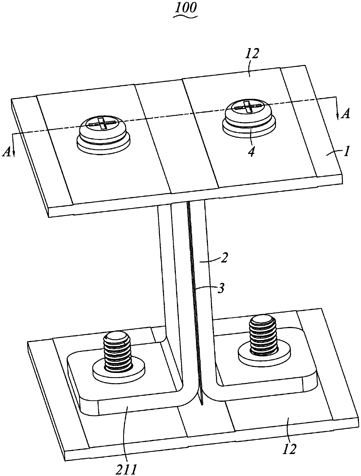
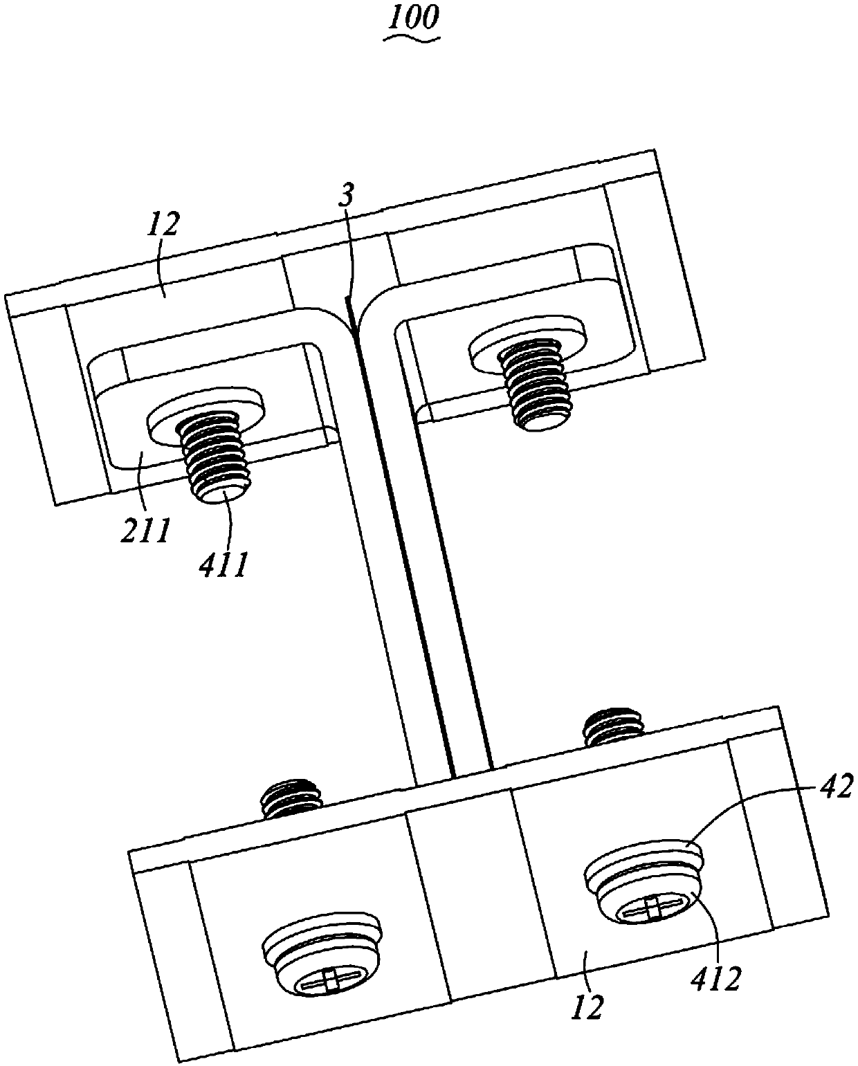
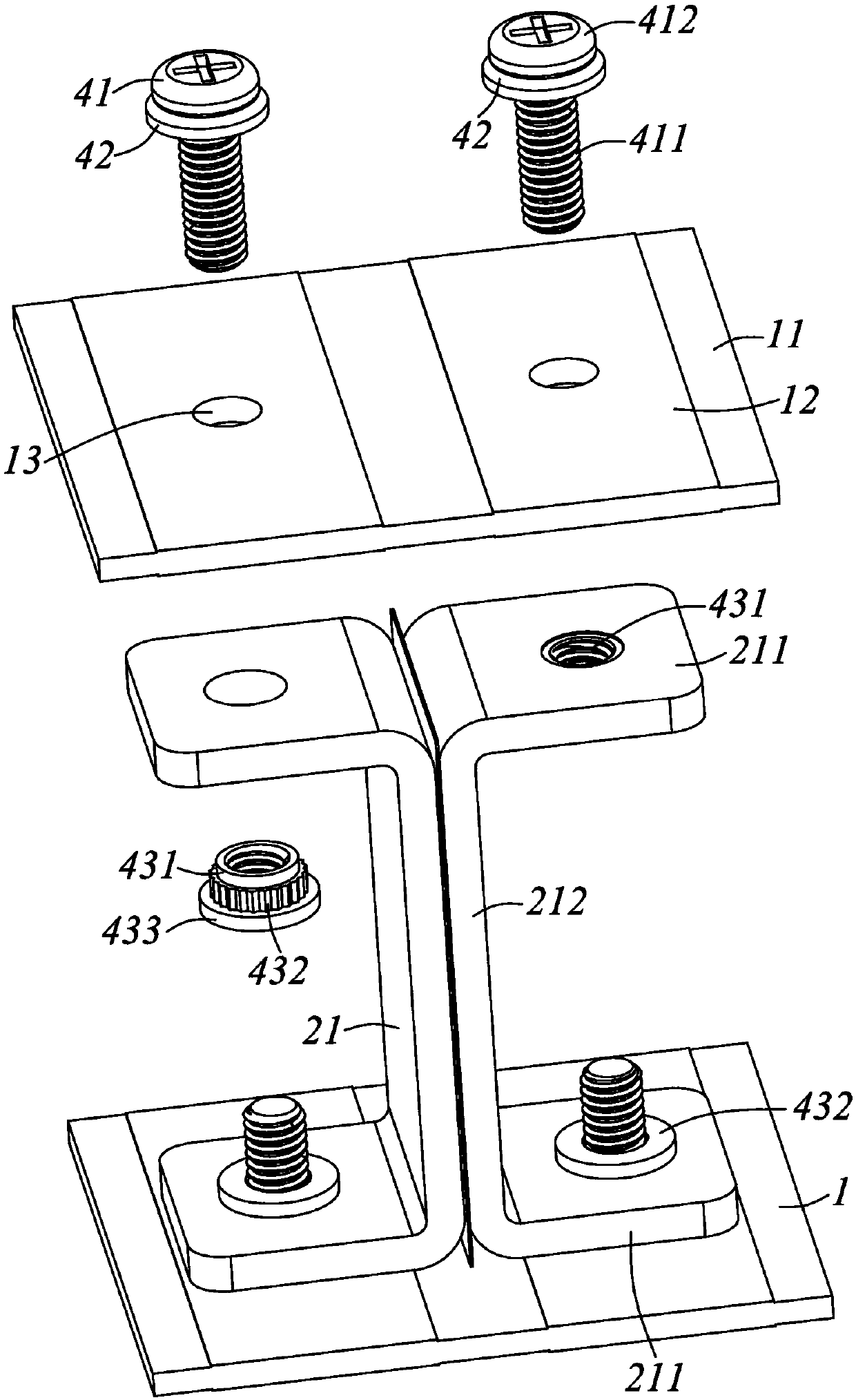
[0026] Please refer to Figure 1 to Figure 6 Shown is a first preferred embodiment of the electrical connector 100 of the present invention, which includes a pair of circuit boards 1 disposed opposite along the height direction and at least one pair of power terminals 2 electrically connected to the pair of circuit boards 1 . For ease of description, the direction in which a pair of circuit boards 1 are arranged at intervals is regarded as the height direction hereinafter, and one direction perpendicular to the height direction is defined as the lateral direction, and the other direction perpendicular to the he...


PUM


Abstract

The present invention provides an electrical connector. The electrical connector comprises a pair of circuit boards oppositely arranged in a height direction and at least one power terminal pair electrically connected with the pair of circuit boards, the power terminal pair is clamped between the pair of circuit boards, the electrical connector is an integral I-shaped, the power terminal pair comprises a pair of power terminals oppositely arranged, and the pair of power terminals are arranged back to back and clamp an insulation piece therebetween. The electrical connector can effectively transmit a large current and has high reliability.

Description

technical field [0001] The invention relates to an electrical connector. Background technique [0002] In a traditional power connector, the distance between the two power terminals of the power terminal pair is relatively close. When a large current is transmitted, the current passes through the power terminals to generate a high temperature, thereby reducing the reliability of the power connector. [0003] In view of this, it is necessary to improve the existing electrical connectors to solve the above problems. Contents of the invention [0004] The purpose of the present invention is to provide an electrical connector capable of transmitting large current and effectively improving reliability. [0005] In order to achieve the purpose of the above invention, the present invention provides an electrical connector, which includes a pair of circuit boards arranged opposite to each other along the height direction and at least one pair of power terminals electrically conne...

Claims


Application Information

Patent Timeline
Patent Type & Authority Applications(China)
IPC IPC(8): H01R12/52H01R12/57H01R4/30
CPCH01R12/52H01R4/30H01R12/57
Inventor 洪永炽杨琇棉刘瑞红
Owner ALLTOP ELECTRONICS SU ZHOU
Learn More