
Biomass boiler and method for using heat energy by biomass boiler

A biomass boiler and biomass fuel technology, which is applied in the direction of combustion methods, lighting and heating equipment, and fuel burned in a molten state, can solve the problem of insufficient research on the characteristics of biomass fuel, which affects the safe and economical operation of boilers, and the volatile content of biomass Advanced problems, to achieve the effect of compact structure, eliminating potential safety hazards, and improving fuel burnout rate

Inactive Publication Date: 2015-06-03
SOUTH CHINA UNIV OF TECH +1
View PDF4 Cites 4 Cited by
  • Summary
  • Abstract
  • Description
  • Claims
  • Application Information

AI Technical Summary

Problems solved by technology

However, because biomass boilers have just started to be implemented, the process of design, transformation and operation is still in the exploratory stage, and the characteristics of biomass fuels are not studied enough. The volatile content of biomass is high, and a large amount of volatile combustion in an instant will lead to concentrated release of heat, making Flashover phenomenon exists in the operation of some biomass boilers
In addition, if the boiler stops the air supply, the fuel continues to fall into the grate from the feed hopper and moves forward accordingly. At this time, the high-temperature flue gas heat transfer and radiation heating of the feed in the furnace will cause volatile components to escape and accumulate. In the furnace area, when it reaches a certain concentration and temperature, it will suddenly burn or even explode, seriously affecting the safe and economical operation of the boiler, and also bringing great safety hazards to production.

Method used


Image

  • Biomass boiler and method for using heat energy by biomass boiler
  • Biomass boiler and method for using heat energy by biomass boiler
  • Biomass boiler and method for using heat energy by biomass boiler

Examples


Embodiment

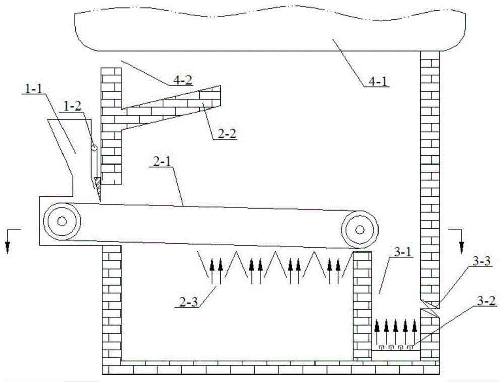
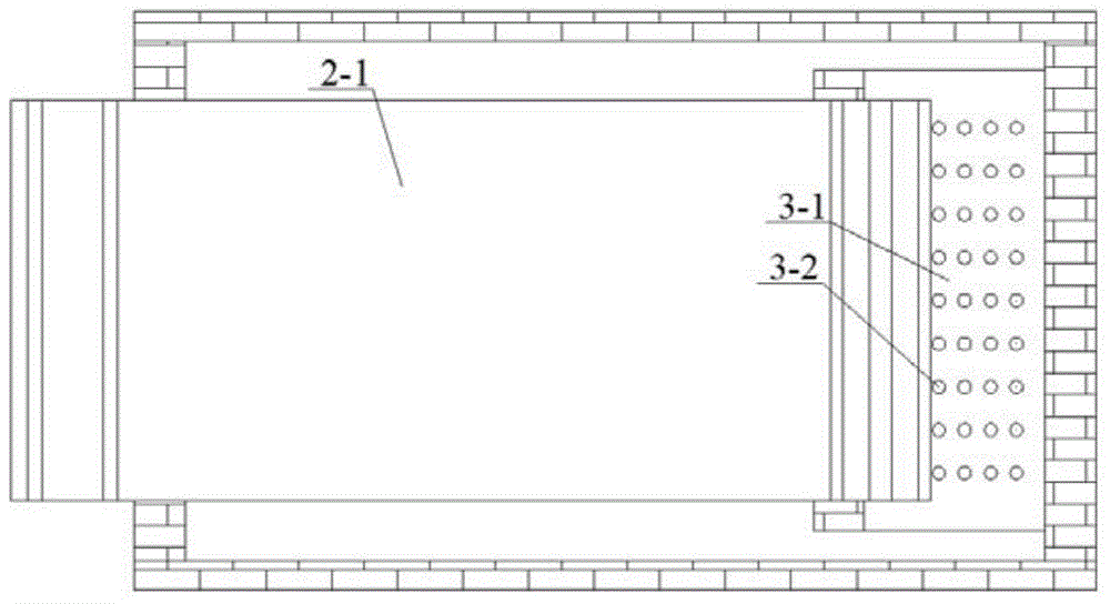
[0031] like figure 1 As shown, the biomass fuel falls into the fire grate from the feed hopper 1-1 and moves in the furnace along with the fire grate. After the air supply port is activated, the isolation door 1-2 rises so that the isolation door rises, and the biomass fuel can move forward into the furnace. When the air supply port is not activated, the isolation door descends under the action of gravity to close the isolation door, preventing further feeding of biomass fuel into the furnace. If the biomass fuel continues to be delivered to the furnace under the condition of insufficient air supply, the biomass fuel will escape volatile matter under the high-temperature radiation of the furnace, and the escaping volatile matter will accumulate in the furnace due to no combustion or insufficient combustion. It is easy to cause flashover accidents; therefore, the isolation door ensures that the biomass fuel is sent into the furnace only when there is air supply in the furnace,...


PUM


Abstract

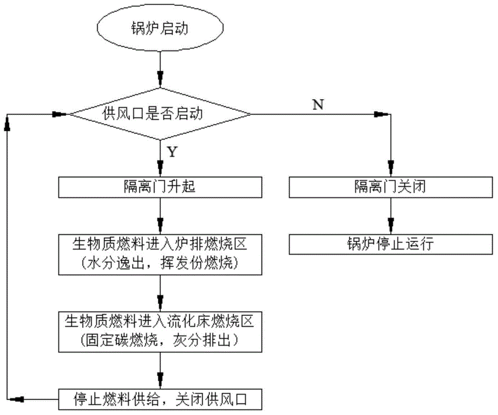
The invention discloses a biomass boiler which comprises a feed hopper, an isolating door, a fire grate, a preposed furnace arch, an air supply opening, a fluidized bed, a cap, a reject valve, a heated face and a smoke outlet. The invention further discloses a method for using heat energy applied to the biomass boiler. The method comprises the following steps: 1, when the boiler is started, detecting whether the air supply opening is started or not, when the air supply opening is started, raising the isolating door and executing a step 2, otherwise, closing the isolating door and executing a step 5; 2, feeding a biomass fuel into the fire grate from the feed hopper, wherein chemical energy in volatile matters of the biomass fuel is converted into heat energy; 3, feeding the biomass fuel into a combustion region of the fluidized bed, wherein the chemical energy in fixed carbon is converted into heat energy, and residual ash is discharged from the reject valve, when the boiler needs to be stopped in operation, executing a step 4; 4, stopping supplying the fuel, closing the air supply opening and executing the step 1; and 5, stopping operation of the boiler. The biomass boiler disclosed by the invention has the advantages that the fuel burnout rate and the boiler combustion efficiency are improved.

Description

technical field [0001] The invention relates to a thermal energy utilization technology, in particular to a biomass boiler and a method for utilizing thermal energy. Background technique [0002] my country is a large agricultural country with a wide range of biomass sources, and biomass fuel has CO 2 Net emission is 0, sulfide, NO x It has excellent environmental protection characteristics such as low emission of heavy metal pollutants, and ash can be returned to the field, which is called green energy and low-carbon energy. At the same time, biomass energy is a renewable energy source. In today's increasingly scarce energy sources, its utilization has great energy strategic significance and is increasingly valued by the country. Biomass boiler is a kind of biomass energy utilization equipment. The main principle is to utilize its heat energy through the combustion of biomass fuel. At this stage, many biomass-fired furnaces are transformed from previous coal-fired furnac...

Claims


Application Information

Patent Timeline
IPC IPC(8): F23C10/00F23C10/18
CPCF23C10/00F23C10/18F23C10/20F23C10/22
Inventor 楼波邬思柯王小聪马括李茂东
Owner SOUTH CHINA UNIV OF TECH
Learn More