
Laparoscopic distraction instruments

A technique for surgery and laparoscopy, which is applied in the field of medical devices, can solve the problems of poor spreading effect of the spreading mechanism, and achieve the effect of good spreading effect, convenient storage, and less space occupied

Inactive Publication Date: 2020-04-14
CHONGQING CANCER INST
View PDF14 Cites 0 Cited by
  • Summary
  • Abstract
  • Description
  • Claims
  • Application Information

AI Technical Summary

Problems solved by technology

[0004] The present invention intends to provide a spreading instrument for laparoscopic surgery to solve the problem of poor spreading effect of the spreading mechanism in the existing laparoscopic surgery

Method used


Image

  • Laparoscopic distraction instruments
  • Laparoscopic distraction instruments
  • Laparoscopic distraction instruments

Examples


Embodiment 1

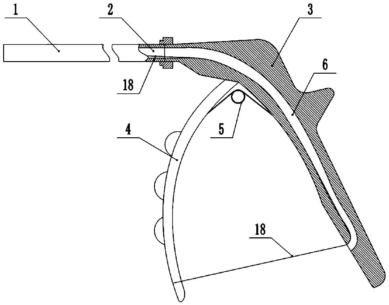
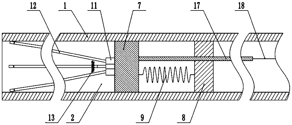
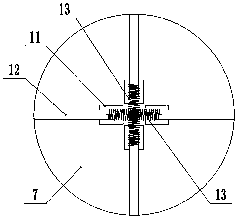
[0030] This embodiment is basically as figure 1 and figure 2 As shown: a stretching instrument for laparoscopic surgery, including an operating rod 1, a first spring 9 and a second spring 13, a through cavity 2 is opened in the operating rod 1, and a handle 3 is fixedly connected to the right end of the operating rod 1. The handle bar 4 is hinged on the 3, and three protrusions are fixedly connected to the handle bar 4, which is convenient for the user to exert force on the hand handle bar 4. A torsion spring 5 is fixedly connected to the handle 3 , and the other end of the torsion spring 5 is fixedly connected to the handle bar 4 . A channel 6 is opened inside the handle part 3 , and the channel 6 communicates with the through cavity 2 .

[0031] A sliding plate 7 is slidably connected in the through cavity 2 of the operating pole 1, and a fixed plate 8 is fixedly connected in the through cavity 2. The fixed plate 8 is located on the right side of the slide plate 7, and th...

Embodiment 2

[0039] The difference between this embodiment and Embodiment 1 is that: figure 1 , Figure 5 and Figure 6 As shown, the sliding plate 7 and the fixed plate 8 form a sealed cavity 10 in the through cavity 2, and each expansion group also includes a cylinder 14 oppositely arranged, and a piston 141 is slidably connected to the cylinder 14, and the piston 141 separates the cylinder 14. For the upper chamber 142 and the lower chamber 143 , the piston 141 is fixedly connected with a piston rod 144 , the end of the piston rod 144 away from the piston 141 is equipped with a collar 15 , and the strut 12 is located in the collar 15 . The slide plate 7 is provided with an air passage 16 , and the air passage 16 communicates with the upper chamber 142 and the sealed chamber 10 . A ventilation hole is opened on the side wall of the lower chamber 143 opposite to the piston 141 so that the inside of the lower chamber 143 communicates with the outside world and reduces the resistance suff...


PUM


Abstract

The invention relates to the technical field of medical instruments, in particular to an opening instrument for a laparoscopic operation, which comprises an operation rod, a first spring and a secondspring, wherein a through cavity is formed in the operation rod, a sliding plate is slidably connected in the through cavity, a fixing plate is fixedly connected in the through cavity, the sliding plate is connected with a fixed plate through the first spring; one side of the sliding plate, away from the fixed plate, is provided with a plurality of opening groups, each opening group comprises twooppositely arranged mounting seats, each mounting seat is hinged with a supporting bar, the two supporting bars are connected through the second spring, one side of the sliding plate, close to the fixed plate, is fixedly connected with a connecting rod, the connecting rod penetrates through the fixed plate, one end of the connecting rod, away from the sliding plate, is fixedly connected with a pull rope. According to the invention, the sliding plate is pulled to slide by pulling the pull rope, so that the plurality of supporting rods can be opened and closed, the operation is convenient, and the opening effect is good. In addition, the supporting rods can be completely folded in the through cavity of the operation rod, so that the volume occupied by the supporting rods during storage is reduced, and the supporting rods are convenient to store.

Description

technical field [0001] The invention relates to the technical field of medical instruments, and specifically discloses a distraction instrument for laparoscopic surgery. Background technique [0002] With the rapid development of industrial manufacturing technology, the integration of related disciplines has laid a solid foundation for the development of new technologies and methods. Coupled with the increasingly skilled operation of doctors, endovascular surgery has gradually developed, greatly increasing the surgical options for patients. . Compared with traditional open surgery, laparoscopic surgery avoids long incisions and helps patients recover. In addition, in laparoscopic surgery, the laparoscopic lens can provide doctors with a wider and clearer field of vision, which is conducive to doctors to complete the operation more smoothly and reduce the risk of surgery. Therefore, as a minimally invasive surgical method, laparoscopic surgery has become very popular. [0...

Claims


Application Information

Patent Timeline
Patent Type & Authority Patents(China)
IPC IPC(8): A61B17/02
CPCA61B17/0218A61B17/0281A61B2017/0225
Inventor 张曦
Owner CHONGQING CANCER INST
Learn More