Supercharge Your Innovation With Domain-Expert AI Agents!

Liquid ejecting device and maintenance method of liquid ejecting device

A spraying device and a technology of a liquid spraying part, which are applied in printing and other directions, can solve the problems of not being able to perform good preliminary spraying, reducing the scraping ability of the scraping part, and hindering the rotation of the polygonal roller.

Active Publication Date: 2019-04-23
SEIKO EPSON CORP
View PDF14 Cites 2 Cited by
  • Summary
  • Abstract
  • Description
  • Claims
  • Application Information

AI Technical Summary

Problems solved by technology

If the remaining ink is thickened in contact with the scraping part, the scraping ability of the scraping part may be reduced, or the rotation of the polygonal roller may be hindered, so that preliminary ejection may not be performed satisfactorily.

Method used


Image

  • Liquid ejecting device and maintenance method of liquid ejecting device
  • Liquid ejecting device and maintenance method of liquid ejecting device
  • Liquid ejecting device and maintenance method of liquid ejecting device

Examples


no. 1 approach

[0031] Hereinafter, a first embodiment of the liquid ejecting device will be described with reference to the drawings.

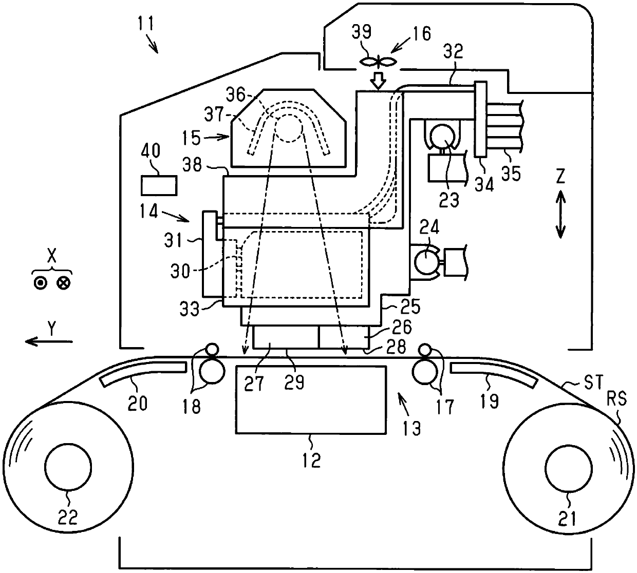
[0032] Such as figure 1 As shown, the liquid ejecting device 11 includes a support base 12 that supports the medium ST, and a transport unit 13 that transports the medium ST in the transport direction Y along the surface of the support base 12 . The liquid ejection device 11 includes a liquid ejection unit 14 that ejects a liquid to the medium ST transported by the transport unit 13 , a heat generating unit 15 and an air blower 16 for drying the liquid adhering to the medium ST.

[0033] The support table 12 is long in the width direction X which is a direction intersecting with the conveyance direction Y within a horizontal plane, and supports the medium ST in the vertical direction Z from below. The conveyance part 13 has conveyance roller pair 17,18 which is arrange|positioned at the upstream side and the downstream side rather than the support table 12 ...

no. 2 approach

[0109] Next, a second embodiment of the liquid ejecting device will be described with reference to the drawings. In addition, in this second embodiment, the timing at which the second turning movement is performed after the first turning movement is performed is different from the case of the first embodiment. In addition, since the other points are basically the same as those of the first embodiment, the same symbols are assigned to the same configurations, and overlapping descriptions will be omitted.

[0110] Figure 18 The maintenance processing program shown is executed when printing is started, as in the first embodiment.

[0111] Such as Figure 18 As shown, in step S201 to step S204, the control unit 40 executes and Figure 11Step S101 to step S104 in the maintenance processing program shown are the same processing.

[0112] In step S205 , the control unit 40 judges whether or not a predetermined period has elapsed after the first turning operation was performed. ...


PUM


Abstract

The invention provides a liquid ejecting device capable of well performing flushing, and a maintenance method of the liquid ejecting device. The liquid ejecting device comprises a liquid ejecting part(14) capable of ejecting a liquid; a first rotating body (112) having a peripheral surface (111) to which the liquid ejected from the liquid eject part (14) can adhere; and a first contact member (135) which comes into contact with the peripheral surface (111) when the first rotating body (112) rotates and collects the first liquid adhering to the peripheral surface (111). The liquid ejecting device performs a first rotating operation for rotating the first rotating body (112) in a first rotating direction in a state in which the peripheral surface (111) and the first contact member (135) arein contact with each other after the liquid ejecting part (14) performs flushing for ejecting liquid toward the peripheral surface (111), and a second rotating operation for, after the first rotationoperation, rotating the first rotation body (112) in the seciond rotating direction in a state in which the peripheral surface (111) and the first contact member (135) are in contact with each other.

Description

technical field [0001] The present invention relates to a liquid ejecting device such as an inkjet printer, and a maintenance method for the liquid ejecting device. Background technique [0002] As an example of a liquid ejecting device, there is an inkjet recording device (such as , Patent Document 1). [0003] In such an inkjet recording device, in order to maintain a good state of ink ejection from the recording head, preliminary ejection (flushing) of ejected ink is performed independently of recording. In the preliminary discharge, the ink is discharged to the polygonal roller (rotating body), and the ink adhering to the polygonal roller is scraped off by the scraping portion (contact member). [0004] When ink is scraped off by the scraping portion, ink may remain on a portion where the scraping portion and the polygonal roller come into contact. If the remaining ink is thickened in contact with the scraping portion, the scraping ability of the scraping portion may ...

Claims


Application Information

Patent Timeline
Patent Type & Authority Applications(China)
IPC IPC(8): B41J2/01B41J2/175
CPCB41J2/01B41J2/17503
Inventor 関隆纪中村史木村仁俊
Owner SEIKO EPSON CORP
Features
  • R&D
  • Intellectual Property
  • Life Sciences
  • Materials
  • Tech Scout
  • Unparalleled Data Quality
  • Higher Quality Content
  • 60% Fewer Hallucinations
Learn More