Bicycle crank shaft rod assembly

A technology for crankshafts and bicycles, which is applied to crank structures, vehicle components, transportation and packaging, etc., can solve the problems of increased mechanical performance requirements, many manufacturing processes, and increased processes, and achieves low mechanical performance requirements, and the manufacturing process is suitable for, Good overall rigidity

Inactive Publication Date: 2019-04-23
雷明久
View PDF5 Cites 1 Cited by
  • Summary
  • Abstract
  • Description
  • Claims
  • Application Information

AI Technical Summary

Problems solved by technology

[0002] The main assembly methods of the crank, shaft and center shaft used in the rotating part of the bicycle today are square hole center shaft and spline center shaft. Their center shaft bearings are installed in the bottom bracket of the frame, and the shaft and shaft The bearing kit of the center shaft is a complete set that can hardly be disassembled and divided. With the bearing installed in the bottom bracket, the installation and disassembly of such structural components is cumbersome and laborious and is easily damaged. Poor, poor life, not suitable for general-purpose standard parts in broad-spectrum industries, and many manufacturing processes; another integrated center shaft structure is to separate the center shaft from the bearing, and directly combine it with the crank on one side , and the position of the bearing is moved from the bottom bracket to the two sides. The disadvantage of this type of structural assembly is that the part where the shaft rod and the crank are integrally connected requires additional strength design or additional fasteners, which leads to low design freedom and poor quality. Larger and there is greater stress in this part, the requirements for the mechanical properties of each material are increased, the requirements for manufacturing precision are also higher, and the number of processes increases, which increases the difficulty of manufacturing and increases the cost.

Method used


Image

  • Bicycle crank shaft rod assembly

Examples


Embodiment 1

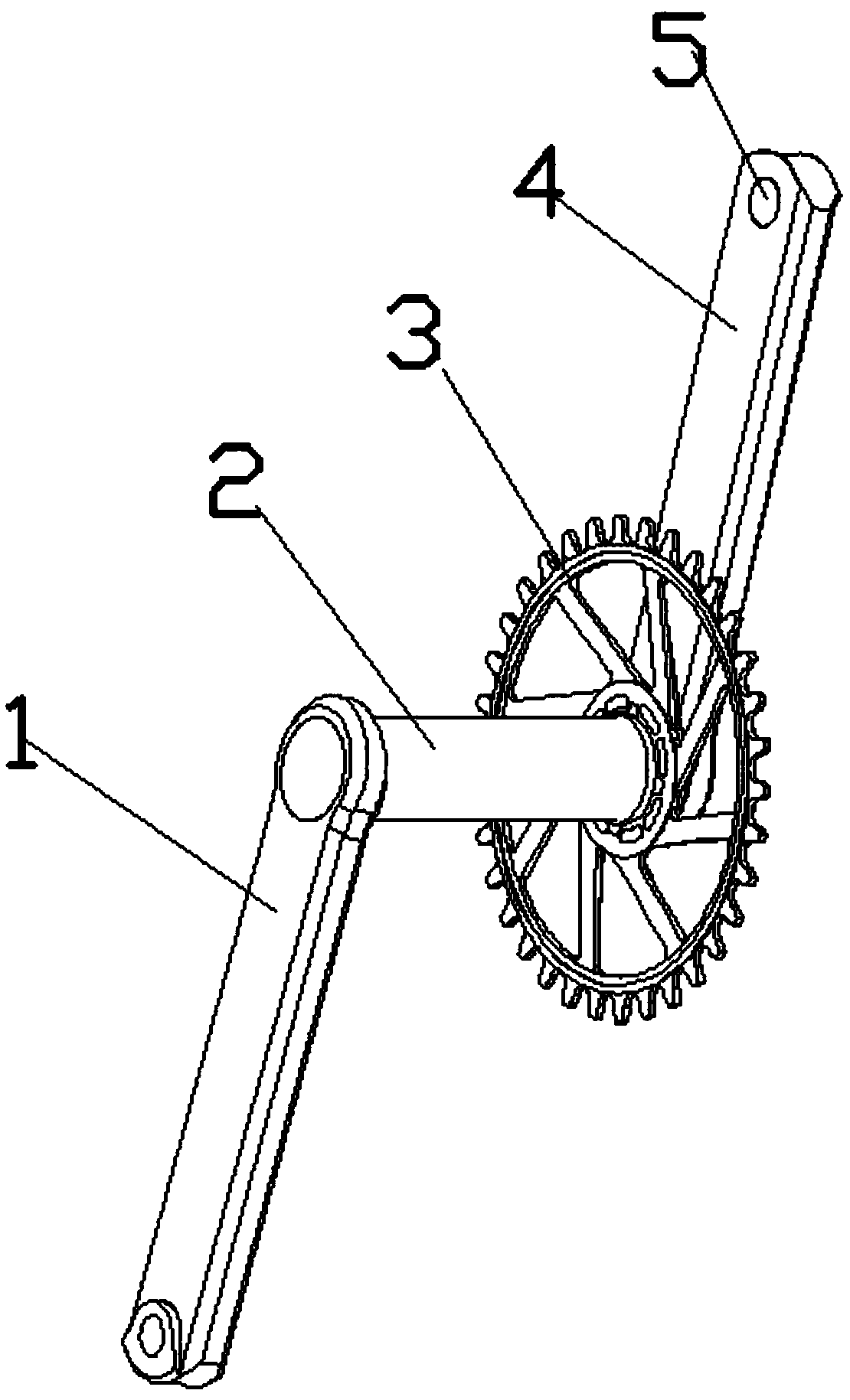
[0023] Such as figure 1 As shown, this embodiment provides a bicycle crank shaft assembly, including a left crank 1, a shaft 2, a chainring 3 and a right crank 4; wherein, the left end of the left crank 1 and the shaft 2 are set as an integrated structure , the right end of the axle rod 2 passes through the crankshaft 3 and is fixedly connected with the right crank 4, and the crankshaft 3 is fixedly connected with the right crank 4.

[0024] Based on the bicycle crank shaft assembly with the above structure, since the left crank and the shaft are integrally formed, the left crank and the shaft do not need to be fixed and installed by locking screws or through additional strength design or additional fasteners, the structure is more It is simple so that it is easier to install and disassemble, and the stress generated is less so that the existing stress is smaller, so the overall rigidity of the crank and the bottom bracket is not easy to deform, and the integral molding struct...

Embodiment 2

[0033] Such as figure 1 As shown, this embodiment provides a bicycle crank shaft assembly, including a left crank 1, a shaft 2, a chainring 3 and a right crank 4; wherein, the left end of the left crank 1 and the shaft 2 are set as an integrated structure , the right end of the axle rod 2 passes through the chain plate 3 and is fixedly connected with the right crank 4, and the chain plate 3 is fixedly connected with the right crank 4.

[0034] Preferably, the right crank 4 and the chainring 3 are integrally formed.

[0035] Based on the bicycle crank shaft assembly with the above structure, since the left crank and the shaft are integrally formed, the right crank and the chainring are also integrally formed; therefore the left crank and the shaft, the right crank and the chainring do not need to pass Tight screw fixed installation or through extra strength design or adding extra fasteners, the structure is simpler and easier to install and disassemble, and the stress generate...


PUM


Abstract

The invention relates to a bicycle crank shaft assembly, which belongs to the field of bicycle parts. The bicycle crank shaft rod assembly comprises a left crank, a shaft rod, a tooth disc and a rightcrank. The bicycle crank shaft rod assembly is characterized in that one ends of the left crank and the shaft rod are of an integrated structure, the other end of the shaft rod penetrates through thetooth disc to be fixedly connected with the right crank, and the tooth disc is fixedly connected with the right crank. According to the bicycle crank shaft rod assembly provided by the invention, byadopting the scheme of integrating the shaft rod and the left crank, no additional locking screw or fastener is used. The bicycle crank shaft rod assembly has the characteristics of simple structure,convenience in installation and disassembly, good overall rigidity, low requirement on mechanical properties of materials, few procedures, low cost and the like.

Description

technical field [0001] The invention belongs to the technical field of bicycle components, and in particular relates to a bicycle crank shaft assembly. Background technique [0002] The main assembly methods of the crank, shaft and center shaft used in the rotating part of the bicycle today are square hole center shaft and spline center shaft. Their center shaft bearings are installed in the bottom bracket of the frame, and the shaft and shaft The bearing kit of the center shaft is a complete set that can hardly be disassembled and divided. With the bearing installed in the bottom bracket, the installation and disassembly of such structural components is cumbersome and laborious and is easily damaged. Poor, poor life, not suitable for general-purpose standard parts in broad-spectrum industries, and many manufacturing processes; another integrated center shaft structure is to separate the center shaft from the bearing, and directly combine it with the crank on one side , and...

Claims


Application Information

Patent Timeline
Patent Type & Authority Applications(China)
IPC IPC(8): B62M3/00
CPCB62M3/00
Inventor 雷明久郑博仁
Owner 雷明久
Why Eureka
Try Eureka