
Emptying system for high dam

A venting system and high dam technology, applied in water conservancy engineering, marine engineering, coastline protection and other directions, can solve the problems of inability to realize deep water retaining and venting, increase in the amount of gate wells, and large gap between gate wells, etc. Quantity and investment, low engineering investment cost, and the effect of eliminating water hammer

Pending Publication Date: 2019-04-23
CHINA POWER CONSRTUCTION GRP GUIYANG SURVEY & DESIGN INST CO LTD
View PDF8 Cites 1 Cited by
  • Summary
  • Abstract
  • Description
  • Claims
  • Application Information

AI Technical Summary

Problems solved by technology

[0004] (1) There is no backup filling and drainage system in the above system, and the balance of water pressure and air pressure is only realized through internal and external connecting pipes, external maintenance connecting pipes, water filling pipes, corridors, etc. Once the connecting pipes fail, the balance of the entire system The pressure effect will also fail, causing the system to be paralyzed and unable to realize the function of deep water blocking and venting;
[0005] (2) In the above system, the working gate and maintenance gate hoist are arranged side by side on the hoist platform. Due to the operating space requirements of the hoist, the distance between the gate wells corresponding to the hoist is too large, and the engineering volume of the gate well increases. , especially for projects with a large gate shaft height, it is bound to greatly increase the project investment

Method used


Image

  • Emptying system for high dam
  • Emptying system for high dam
  • Emptying system for high dam

Examples


Embodiment Construction

[0031] The technical solution of the present invention is further described below in conjunction with the accompanying drawings, but the scope of protection is not limited to the description.

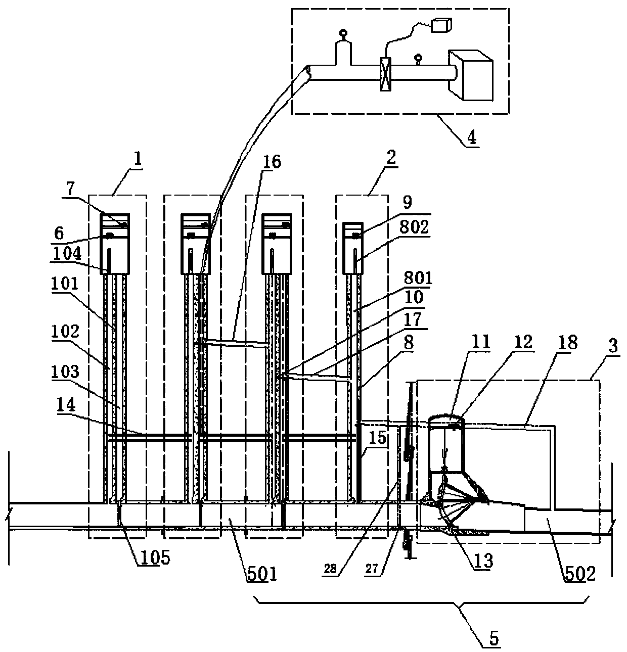
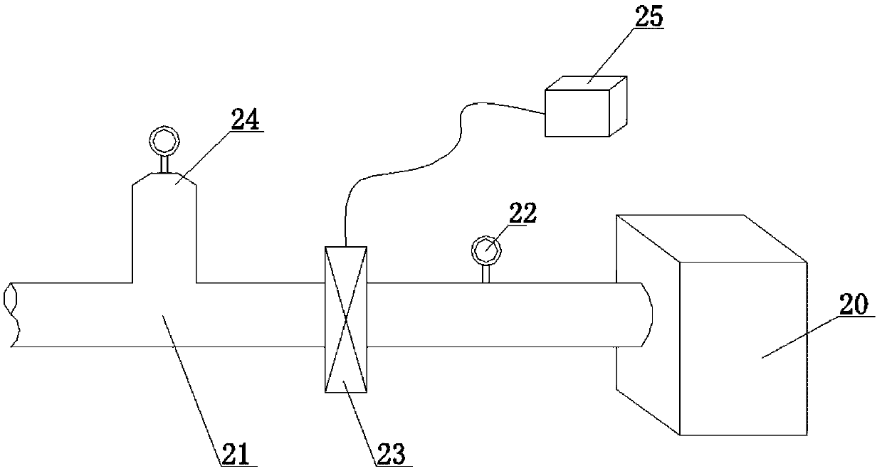
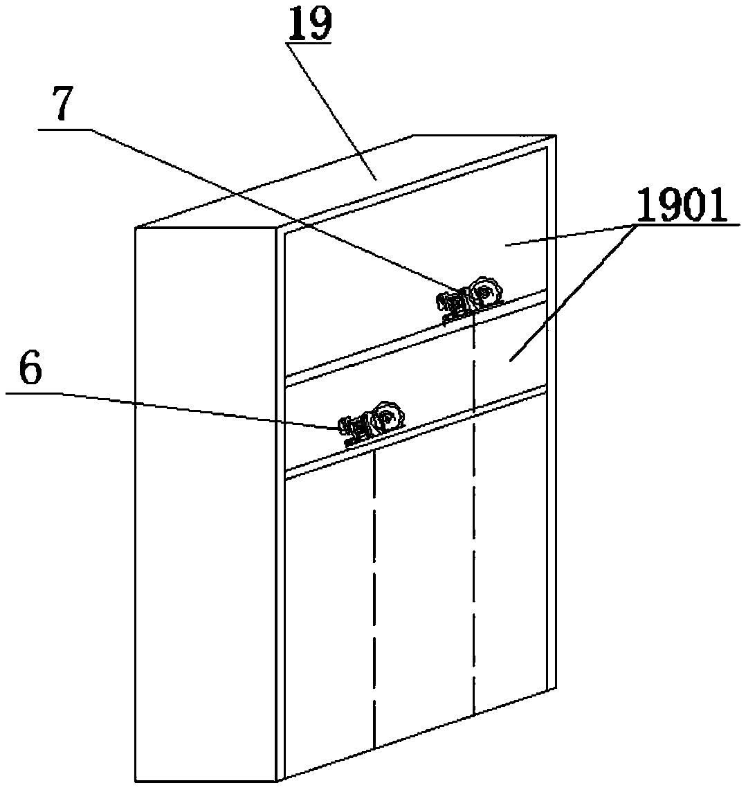
[0032] The invention provides a high dam emptying system, such as figure 1 , figure 2 , image 3 As shown, a tunnel 5 and a water replenishment unit 4 are included, and along the water flow direction inside the tunnel 5, a plurality of primary gate devices 1, at least one secondary gate device 2 and at least one emptying gate are arranged in sequence on the tunnel 5 at appropriate intervals Device 3, the tunnel 5 upstream of the emptying gate device 3 is a pressurized section 501, and the tunnel 5 downstream of the emptying gate device 3 is a non-pressure section 502. The primary gate device 1 includes a primary gate body 101, which flows along the direction of water flow in the tunnel 5 In the primary gate body 101, an inspection gate shaft 102 and a working gate shaft 103 are arran...


PUM


Abstract

The invention discloses an emptying system for a high dam. The emptying system comprises a plurality of primary gate devices, secondary gate devices and an emptying gate device successively arranged along a flow direction of river water, wherein each primary gate device comprises an overhaul gate well and a working gate well arranged in parallel and a power device A and a power device B arranged on the top; each secondary gate device comprises an accident gate well and a power device C arranged on the top; the overhaul gate well, the working gate well and the accident gate well can be independently opened and closed; a water replenishing unit which is independently arranged on the exterior is used for replenishing the working gate in the second secondary gate device with water; the emptying gate device comprises an emptying lock chamber and an arc-shaped emptying gate. According to the technical scheme of the invention, pressure of upstream water head can be shared by the plurality ofprimary gate devices; reservoir water can be emptied by the emptying gate device; water pressure in the system is replenished by the water replenishing unit, so that flow rate of water can be kept stable, the gate devices can be prevented from bearing ultrahigh water head pressure and safety and stability of the whole system can be guaranteed.

Description

technical field [0001] The invention belongs to the technical field of water conservancy and hydropower engineering, and in particular relates to a high dam emptying system. Background technique [0002] With the development of dam engineering technology and the emergence of 300m high dams, higher requirements are put forward for the venting and operation of the project. However, at present, the general venting facilities can only vent the reservoir water to a water depth of about 105m. The reason is mainly affected by the level of gate manufacturing technology, which limits the design of the gate's retaining head, resulting in potentially catastrophic accidents and huge economic losses. Therefore, it is necessary to propose a venting structure that can meet the existing metal structure manufacturing level and increase the venting depth, so as to vent the reservoir water of the 300-level high dam project as much as possible, and ensure the safety of the project to the greate...

Claims


Application Information

Patent Timeline
Patent Type & Authority Applications(China)
IPC IPC(8): E02B8/04E02B7/20E02B8/06
CPCE02B7/20E02B8/04E02B8/06
Inventor 杨家修杜帅群湛正刚姚元成郑雪玉鲍伟
Owner CHINA POWER CONSRTUCTION GRP GUIYANG SURVEY & DESIGN INST CO LTD
Learn More