
Automobile transmission shaft torsion damper

A technology of a torsional shock absorber and a transmission shaft, which is applied in the field of automobile transmission system, can solve the problems of worsening the vibration of the floor seat in the car, the noise in the car, the overturning deformation of the coupling, and the change of the included angle, etc., so as to ensure the power transmission. , the effect of reducing noise and improving ride comfort

Inactive Publication Date: 2019-04-23
CHONGQING CHANGAN AUTOMOBILE CO LTD
View PDF5 Cites 5 Cited by
  • Summary
  • Abstract
  • Description
  • Claims
  • Application Information

AI Technical Summary

Problems solved by technology

For the integral rear axle, the traditional flexible coupling is only installed between the transmission output shaft and the transmission shaft, not between the transmission shaft and the rear axle; the reason is that the movement of the rear axle is complex during the driving of the car, There will be a large amount of displacement in the up and down direction, front and rear direction, the angle between the transmission shaft and the rear axle pinion changes greatly, and it is difficult to maintain a small value; when the angle between the transmission shaft and the rear axle is too large , if you continue to use the traditional flexible coupling, it will cause the coupling to overturn and deform, and at the same time bring high-order vibration, which will worsen the interior floor, seat vibration and interior noise

Method used


Image

  • Automobile transmission shaft torsion damper
  • Automobile transmission shaft torsion damper
  • Automobile transmission shaft torsion damper

Examples


Embodiment Construction

[0025] The present invention will be described in detail below in conjunction with the accompanying drawings and embodiments.

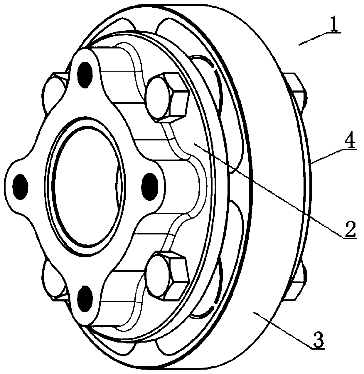
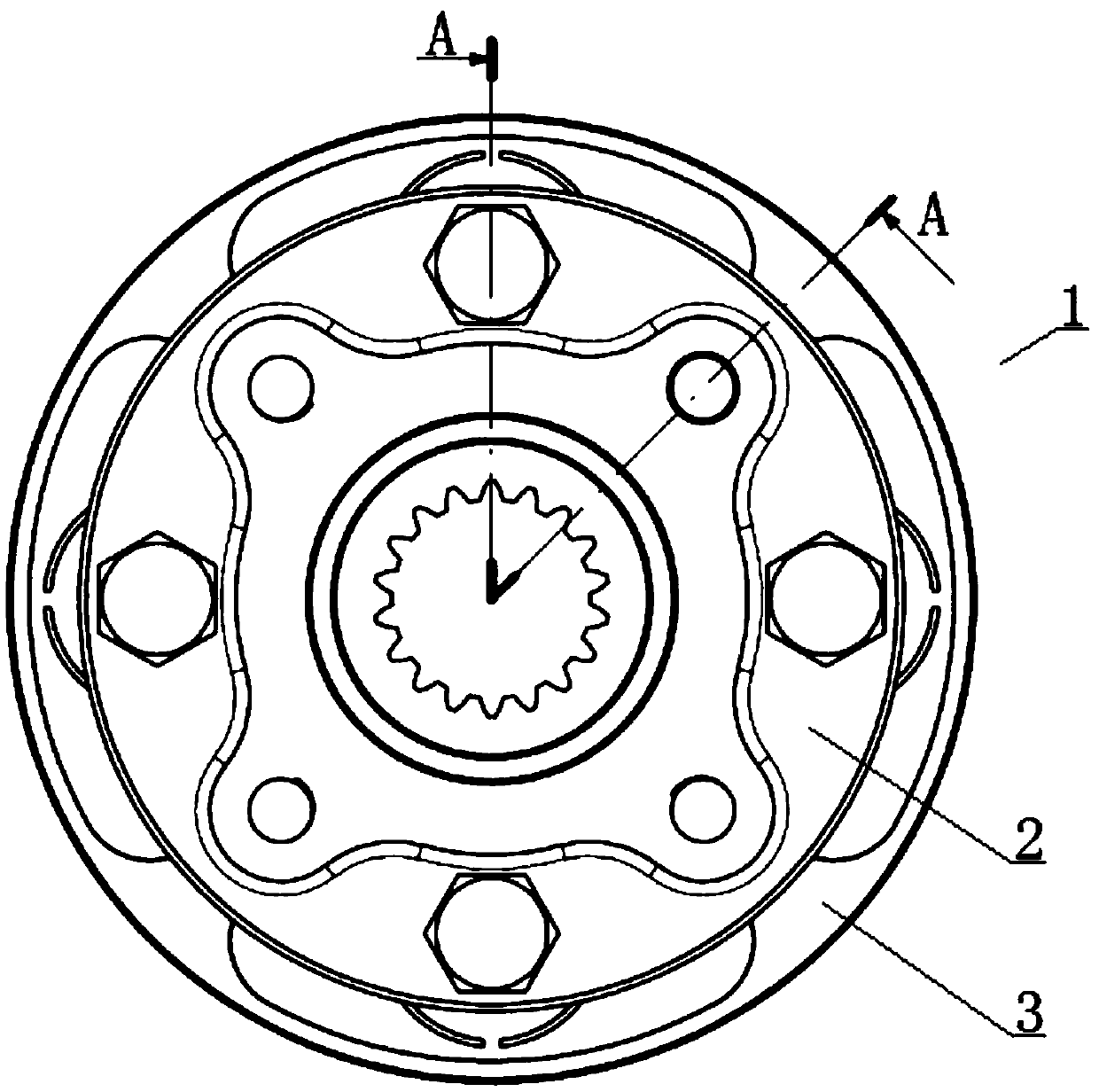
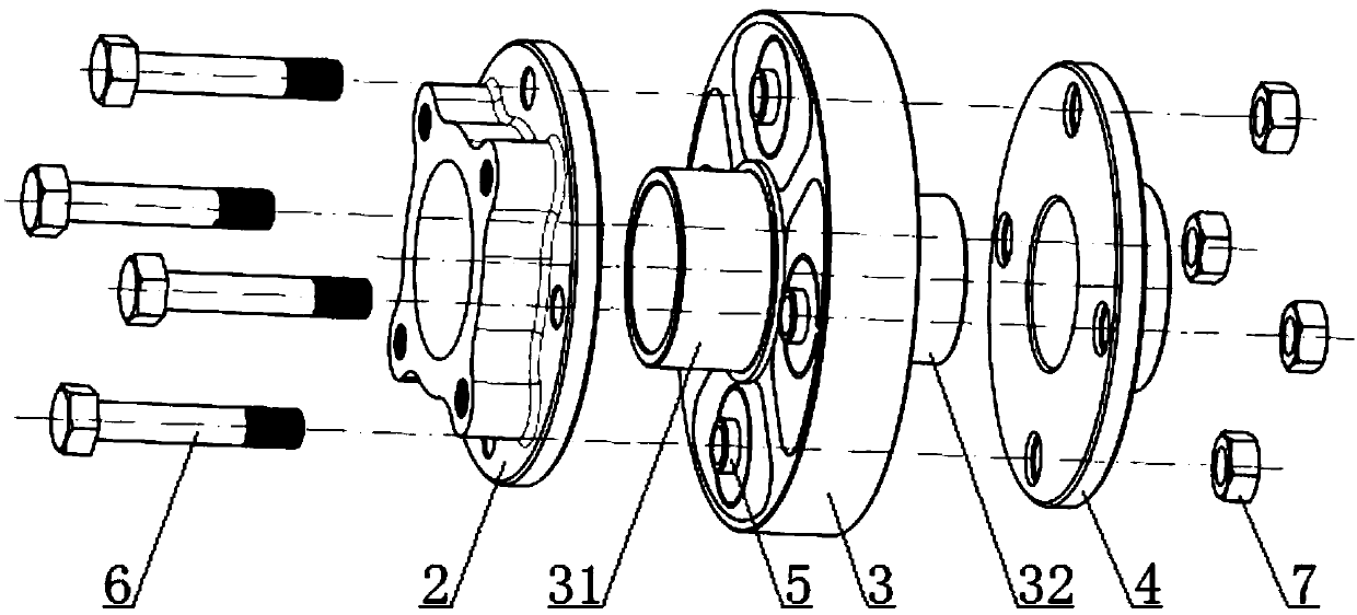
[0026] see Figure 1 to Figure 8 The shown torsional shock absorber for a transmission shaft of an automobile includes a torsional shock absorber body 1 that is arranged between the drive shaft 9 and the pinion shaft 10 of the final drive and is connected with both, and is characterized in that: the torsional The shock absorber body 1 includes a driving flange 2 that is mated with the transmission shaft 9, a driven flange 3 that is matched with the driving flange 2 at the front, and a driven flange 3 that is matched with the rear of the driven flange 3 and that is connected with the driven flange 3. The supporting flange 4 fastened to the active flange 2; the active flange 2, the driven flange 3 and the supporting flange 4 are coaxially arranged, and the driven flange 3 is connected to the active flange 2 and The supporting flanges 4 are axial cleara...


PUM


Abstract

The invention relates to an automobile transmission shaft torsion damper. The automobile transmission shaft torsion damper comprises a torsion damper body and is characterized in that the torsion damper body comprises an active flange connected with a transmission shaft in a matched manner, a driven flange with the front portion matched with the active flange, and a supporting flange matched withthe rear portion of the driven flange and connected with the active flange in a fastening manner; the active flange, the driven flange and the supporting flange are coaxially arranged, and the drivenflange is in axial clearance fit with the active flange and the supporting flange; and an inner spline is arranged in the middle portion and the rear portion of the driven flange, and a main speed reducer small gear shaft is matched with the inner spline of the driven flange. By means of the automobile transmission shaft torsion damper, the additional bending moment brought by the included angle of the transmission shaft can be resisted, the overturning effect caused by a universal joint can be effectively resisted, and the automobile transmission shaft torsion damper is suitable for the condition where the included angle of the transmission shaft and a rear axle is large; the transmission smoothness can be improved; and the impacts of a rear axle gear can be buffered, noise is lowered, and power transmission during normal running of vehicles can also be ensured.

Description

technical field [0001] The invention relates to an automobile transmission system, in particular to a torsional shock absorber for an automobile transmission shaft. Background technique [0002] With the development of automobile technology, users are paying more and more attention to automobile vibration and noise. For rear-drive vehicles, the transmission shaft and the rear axle are the key components of the transmission system. The front end of the pinion gear of the main reducer of the rear axle is connected to the transmission shaft. There will be collisions or even repeated collisions between the small gear and the large gear of the reducer, and the collision will generate a lot of noise and shock vibration when it is transmitted to the car. To solve this problem, it is necessary to add a flexible connection device capable of alleviating impact between the pinion shaft of the rear axle final drive and the transmission shaft. At present, flexible couplings are mainly ...

Claims


Application Information

Patent Timeline
Patent Type & Authority Applications(China)
IPC IPC(8): F16F15/124
CPCF16F15/124
Inventor 张志军唐禹夏元烽徐建春王红英
Owner CHONGQING CHANGAN AUTOMOBILE CO LTD
Learn More