
Power distribution box suitable for intelligent power grid

A technology of smart grid and distribution box, applied in substation/distribution device casing, substation/switchgear cooling/ventilation, electrical components, etc., can solve problems such as low safety, loss, affecting power supply, etc. Convenient, easy to move and fix, the effect of increasing safety

Active Publication Date: 2019-04-23
湖南恒力通电气设备科技有限公司
View PDF8 Cites 10 Cited by
  • Summary
  • Abstract
  • Description
  • Claims
  • Application Information

AI Technical Summary

Problems solved by technology

The distribution box is not easy to move, and the direct contact with the ground has poor moisture resistance. It is easy to affect the use of internal electrical components in rainy days, and the safety is low. The box door does not have a safety lock. Once the box door is opened illegally to steal components, It will cause a lot of loss and affect the power supply

Method used


Image

  • Power distribution box suitable for intelligent power grid
  • Power distribution box suitable for intelligent power grid
  • Power distribution box suitable for intelligent power grid

Examples


specific Embodiment approach 1

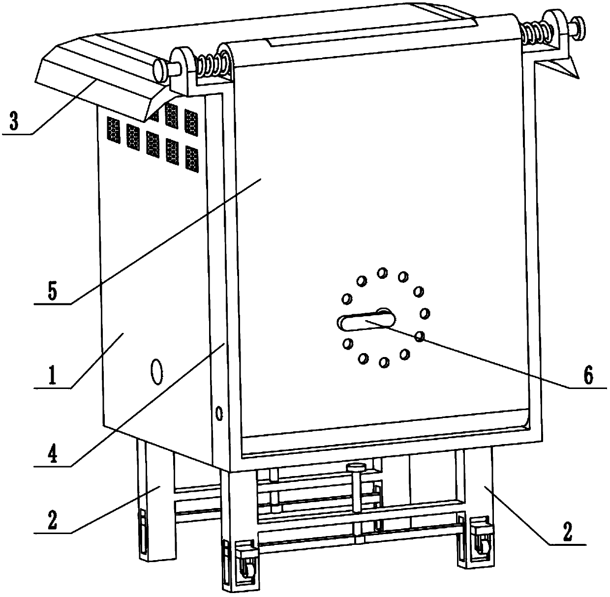
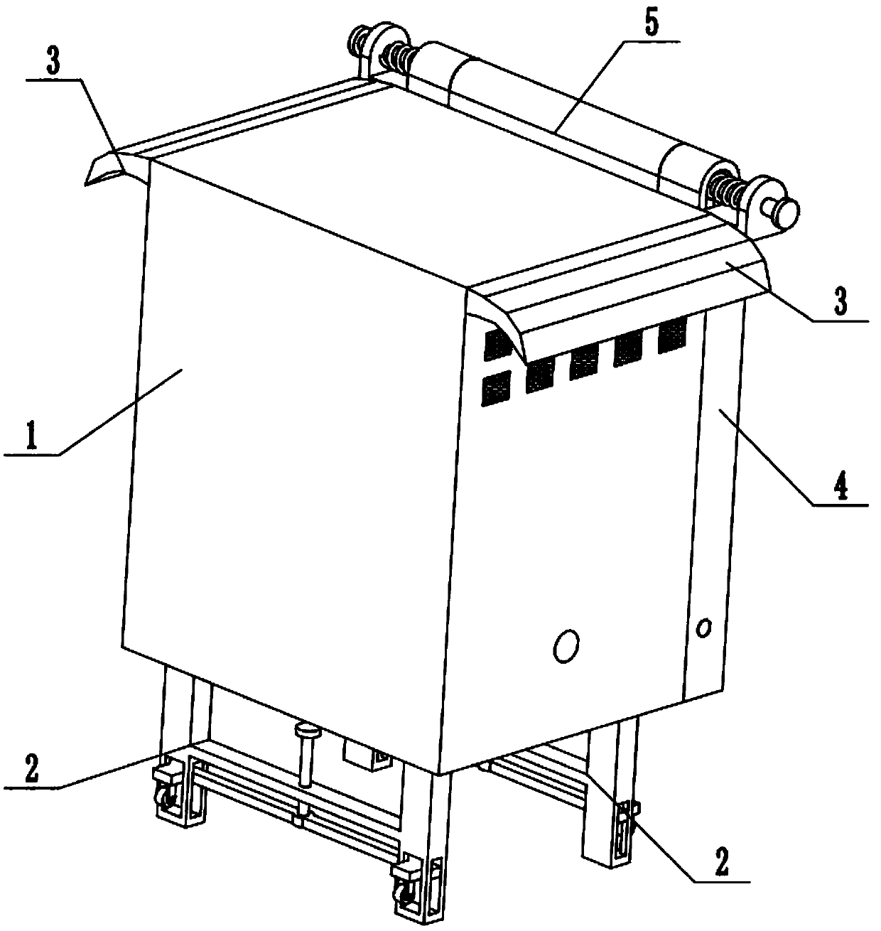
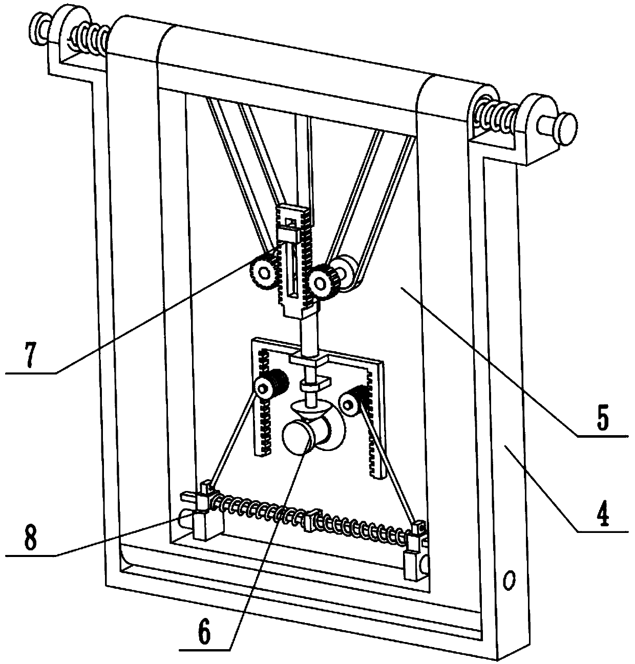
[0033] Combine below Figure 1-15 Describe this embodiment, a distribution box suitable for smart grids, including a distribution box 1, a support leg assembly 2, a rain shield 3, a door frame assembly 4, a door 5, a door control assembly 6, and an upper locking member 7 and the lower locking member 8, the support leg assembly 2 and the rain shield 3 are provided with two, the two support leg assemblies 2 are symmetrically fixedly connected to the front and rear ends of the bottom surface of the distribution box 1, and the two rain shields The board 3 is symmetrically and fixedly connected to the left and right ends of the upper end of the distribution box 1, the door frame assembly 4 is fixedly connected to the front end of the distribution box 1, the box door 5 is fitted in the door frame assembly 4 with a gap, and the upper end of the door frame assembly 4 is stuck on the box door 5, the door control assembly 6 is rotatably connected to the middle end of the door 5, the upp...

specific Embodiment approach 2

[0034] Combine below Figure 1-15 To illustrate this embodiment, the front end of the distribution box 1 is hollowed out; the two ends of the upper end of the distribution box 1 are respectively provided with a plurality of vents; the inner side of the vent is fixedly connected to the dust-proof net; Rain plate 3 is positioned at the top of radiating opening. The heat generated inside the distribution box 1 can be discharged from the heat dissipation port, thereby ensuring the normal operation of the distribution box; the rain shield 3 is located above the heat dissipation port, which plays a role of waterproof and dustproof, and prevents dust and rainwater from entering through the heat dissipation port. In the distribution box 1, the dust-proof net prevents dust from entering the distribution box 1 and affecting the performance of the instrument.

specific Embodiment approach 3

[0035] Combine below Figure 1-15 To illustrate this embodiment, the support leg assembly 2 includes a beam 2-1, a vertical leg 2-2, a connecting rod 2-3, a rectangular block 2-4, a wheel frame plate 2-5, a roller 2-6 and a long Screw 2-7; the two ends of the beam 2-1 are respectively fixedly connected to a vertical leg 2-2, and the lower ends of the two vertical legs 2-2 are respectively provided with a rectangular slot, and the two ends of the connecting rod 2-3 slide respectively Connected in the rectangular through grooves at the lower ends of the two vertical legs 2-2, the two ends of the connecting rod 2-3 are respectively fixedly connected to a rectangular block 2-4, and the two rectangular blocks 2-4 are respectively slidably connected to two vertical In the vertical limit chute of the lower end of the support leg 2-2; the lower end of the rectangular block 2-4 is fixedly connected to the two wheel frame plates 2-5, and the roller 2-6 is connected to the two wheel fram...


PUM


Abstract

The invention relates to the field of power distribution boxes and more specifically relates to a power distribution box suitable for an intelligent power grid. Two supporting leg assemblies and two rainproof plates are arranged, the two supporting leg assemblies are symmetrically and fixedly connected to the front end and the rear end of the bottom surface of the power distribution box, the two rainproof plates are symmetrically and fixedly connected to the left end and the right end of the upper end of the power distribution box, a door frame assembly is fixedly connected to the front end ofthe power distribution box, a box door is in clearance fit in the door frame assembly, the upper end of the door frame assembly is clamped to the upper end of the box door, and a box door control assembly is in rotary connection to the middle end of the box door. The power distribution box disclosed by the invention is prevented from being damaged by ground pollutants and water, a power distribution cabinet body has a heat radiating function, the box door can be locked in the door frame assembly by a lower locking assembly, the box door is prevented from being pried by illegal staff, components and parts are prevented from being stolen, and loss is avoided; meanwhile, the box door can slide to the upper end of the power distribution box when in an open state, so that the box door is prevented from being opened or closed by mistake in a work process of workers, the box door is also prevented from being bumped by the workers by accident in the work process, and safety is improved.

Description

technical field [0001] The invention relates to the field of distribution boxes, in particular to a distribution box suitable for smart grids. Background technique [0002] The existing patent number is a new type of distribution box CN201520026304.5. This utility model relates to the field of power distribution, especially a new type of distribution box. The distribution box includes a handle, a cover plate, a right side wall, a door, a bottom plate, a left side wall and a rear wall, an air inlet is provided between the cover plate and the right side wall, the door, the left side wall and the rear wall, Air inlet holes are arranged on the right side wall and the left side wall. A new type of distribution box involved in this utility model is designed with an air inlet and an air inlet, so that the heat generated inside the distribution box can be dissipated from the air inlet and air inlet in time, thus ensuring that the distribution box Normal operation makes people's pr...

Claims


Application Information

Patent Timeline
Patent Type & Authority Applications(China)
IPC IPC(8): H02B1/46H02B1/56H02B1/28
CPCH02B1/28H02B1/46H02B1/565
Inventor 王玉莲
Owner 湖南恒力通电气设备科技有限公司
Learn More