
Condensation generation determination method and device, condensation control method and device, and electronic device

A technology of condensation and equipment, applied in the direction of non-electric variable control, control/regulation system, and simultaneous control of multiple variables, etc., can solve problems such as failure to use normally, damage to switch cabinets, and electrical failures in switch cabinets

Inactive Publication Date: 2019-04-23
GUANGDONG POWER GRID CO LTD +1
View PDF2 Cites 6 Cited by
  • Summary
  • Abstract
  • Description
  • Claims
  • Application Information

AI Technical Summary

Problems solved by technology

Especially in the process of overhauling the switchgear, it is inevitable to repeatedly open and close the cabinet door of the switchgear, which will cause the humid air in the external environment to continuously enter the inside of the cabinet, thus causing The probability of condensation is greatly increased. The accumulation of condensation will cause various electrical failures in the switchgear. In severe cases, it will even damage the switchgear and make it unable to use normally.
At present, it is impossible to effectively predict the generation of condensation in the switch cabinet, and thus it is impossible to take effective measures

Method used


Image

  • Condensation generation determination method and device, condensation control method and device, and electronic device
  • Condensation generation determination method and device, condensation control method and device, and electronic device
  • Condensation generation determination method and device, condensation control method and device, and electronic device

Examples


Embodiment 1

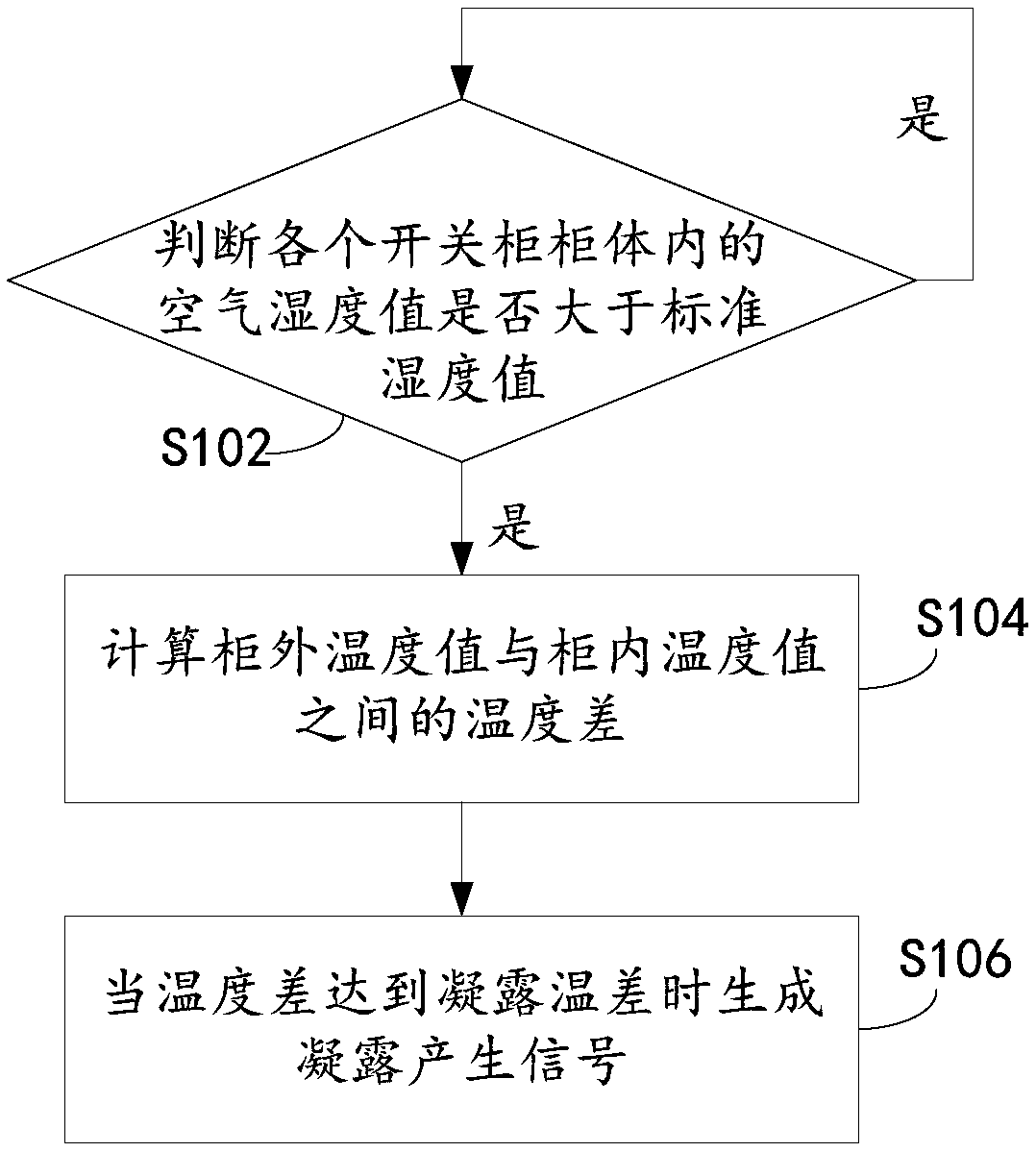
[0048] see figure 1 , the method for judging the generation of condensation proposed in this embodiment, the method is applied to the server, and specifically includes the following steps:

[0049] Step S102: judging whether the air humidity value in each switchgear cabinet is greater than the standard humidity value.

[0050]It should be noted that in the application process of power equipment, the main function of the switchgear is to open and close, control and protect electrical equipment during the process of power generation, transmission, distribution and power conversion in the power system. In order to facilitate management, usually a plurality of switch cabinets are placed together in one area, and each switch cabinet is connected to the above-mentioned server respectively.

[0051] During the implementation process, the server receives the air humidity values ​​from each switch cabinet respectively. When it comes to the condensation judgment of a single switch cabi...

Embodiment approach

[0052] A preferred embodiment of obtaining the above-mentioned air humidity value is given below, which specifically includes the following process:

[0053] (1) The air humidity data collected by the humidity sensor is sampled at preset time intervals, wherein the humidity sensor corresponds to a single switch cabinet.

[0054] In order to collect the air humidity value in the switch cabinet more accurately and effectively, the humidity sensor in the switch cabinet is used for data collection. During implementation, the humidity sensor collects air humidity data continuously. In order to simplify the amount of calculation, the air humidity data collected by the humidity sensor is sampled according to the preset time interval. The preset time interval can be flexibly set according to the actual usage scenario. The preset time interval, in areas with low air humidity, 30 minutes is used as a preset time interval.

[0055] It should be noted that the specific installation posi...

Embodiment 2

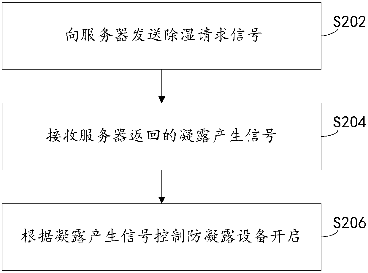
[0076] The accumulation of condensation in the switchgear will cause various electrical failures in the switchgear, and even damage the switchgear so that it cannot be used normally. After effectively judging the generation of condensation in the switch cabinet, it is necessary to take further corresponding treatment measures to remove the condensation generated in the switch cabinet. Therefore, the controller and the corresponding heating device, dehumidification device, etc. are pre-installed inside the control cabinet, and the specific installation positions of the controller, heating device, and dehumidification device can be flexibly set according to the use of the switch cabinet. Especially when there are multiple switchgears, in order to eliminate condensation accurately, the elimination process is carried out individually according to each different control cabinet, which can effectively save resources.

[0077] see figure 2 , this embodiment provides a condensation ...


PUM


Abstract

The present invention provides a condensation generation determination method and device, a condensation control method and device, and an electronic device, and relates to the technical field of electric devices. The condensation generation determination method is applied to a server and comprises the steps of: determining whether an air humidity value in each switch cabinet body is larger than astandard humidity value or not, wherein it should be noted that the standard humidity value is the lowest humidity value capable of generating condensation; if yes, namely, on the premise that the air humidity value in the current switch cabinet body is enough large, calculating temperature difference between a temperature value at the outer portion of the cabinet and a temperature value at the inner portion of the cabinet, namely, determining whether the temperature value in the cabinet has reaches the requirement of generating condensation or not through comparison, and if the temperature difference reaches the condensation temperature value, generating condensation generation signals, namely, determining the generation opportunity of the condensation through dual comparison of the airhumidity value and the temperature value in the switch cabinet. The condensation generation determination method and device, the condensation control method and device, and the electronic device are accurate and convenient.

Description

technical field [0001] The present invention relates to the technical field of power equipment, in particular to a condensation generation judgment method, a control method, a device and electronic equipment. Background technique [0002] During the use of the switchgear, condensation often occurs due to the influence of temperature and humidity in the external environment and the airtightness of the cabinet itself. Especially in the process of overhauling the switchgear, it is inevitable to repeatedly open and close the cabinet door of the switchgear, which will cause the humid air in the external environment to continuously enter the inside of the cabinet, thus causing The probability of condensation is greatly increased, and the accumulation of condensation will cause various electrical failures in the switchgear. In severe cases, it will even damage the switchgear and make it unable to use normally. However, at present, it is impossible to effectively predict the genera...

Claims


Application Information

Patent Timeline
Patent Type & Authority Applications(China)
IPC IPC(8): H02B1/56G05D27/02
CPCG05D27/02H02B1/565
Inventor 杨芳唐小亮周亚兵唐先志杨志
Owner GUANGDONG POWER GRID CO LTD
Learn More