Sterilizing device for medical instruments in delivery rooms

A technology for medical equipment and disinfection devices, applied in disinfection, water supply devices, sanitary equipment for toilets, etc., can solve problems such as low disinfection efficiency, and achieve the effect of improving disinfection effect, reasonable design, and shortening disinfection time.

Inactive Publication Date: 2019-04-26
HEBI COLLEGE OF VOCATION & TECH
View PDF10 Cites 2 Cited by
  • Summary
  • Abstract
  • Description
  • Claims
  • Application Information

AI Technical Summary

Problems solved by technology

[0004] The existing disinfection of medical instruments in the delivery room is to put them into a disinfectant solution for soaking and disinfection, and then pour out the disinfectant solution after soaking. In this disinfec

Method used


Image

  • Sterilizing device for medical instruments in delivery rooms
  • Sterilizing device for medical instruments in delivery rooms
  • Sterilizing device for medical instruments in delivery rooms

Examples


Embodiment 1

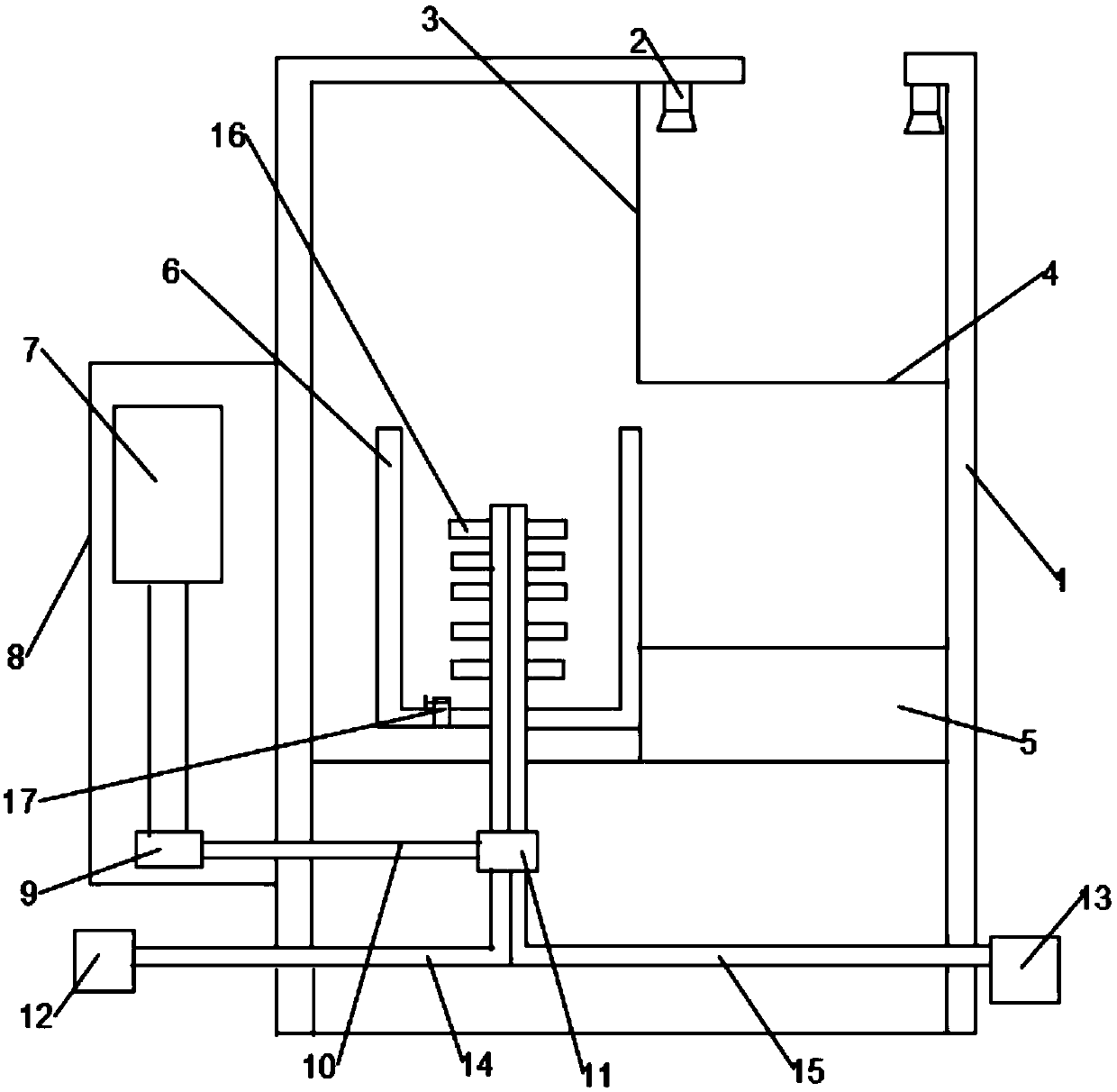
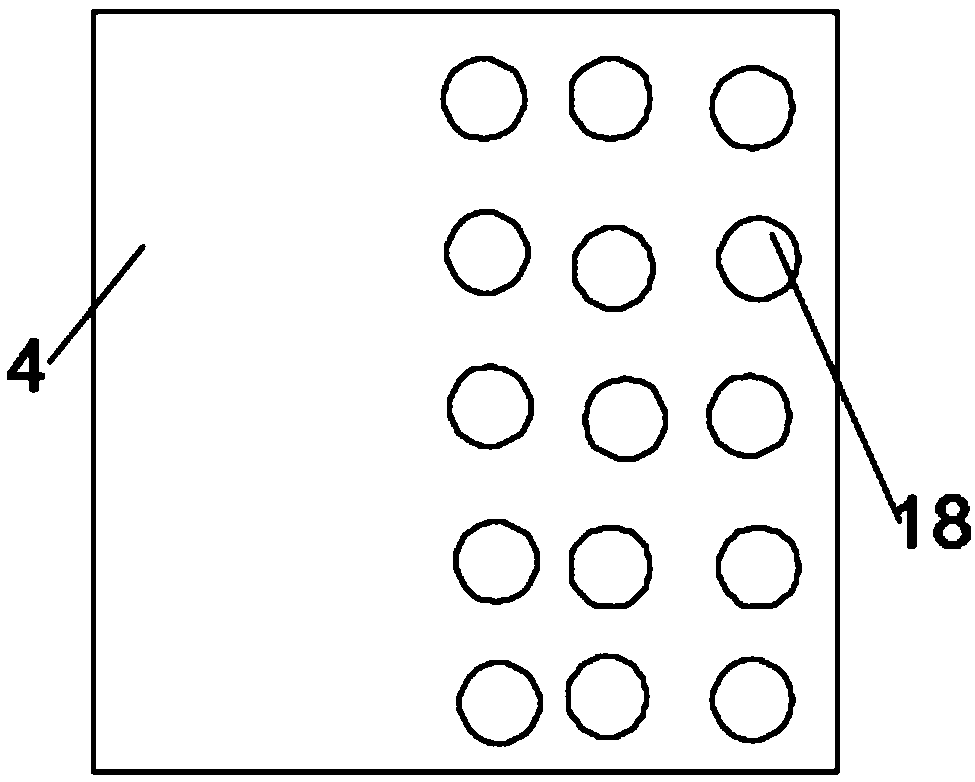
[0023] A disinfection device for medical instruments in the delivery room, comprising a body 1, an opening is provided on the upper end of the body 1 and a cleaning box 3 is installed below the opening, a spray device 2 is installed on the top of the cleaning box 3, and the bottom of the cleaning box 3 is movable There is a movable plate 4 and a plurality of water leakage holes 18 are arranged on the side of the movable plate 4 close to the inner wall. A stirring tank 6 and a waste water tank 5 are also installed in the body 1. The waste water tank 5 is located directly below the cleaning tank 3, and the stirring tank 6 is tightly closed. There is a slight gap between the waste water tank 5 and the mixing box 6 and the movable plate 4. A rotating shaft is arranged in the mixing box 6 and a drain port 17 is provided at the bottom of the mixing box 6. A connecting pipe is arranged inside the rotating shaft and a connecting pipe is provided on the connecting pipe. The liquid outle...

Embodiment 2

[0028] A disinfection device for medical instruments in the delivery room, comprising a body 1, an opening is provided on the upper end of the body 1 and a cleaning box 3 is installed below the opening, a spray device 2 is installed on the top of the cleaning box 3, and the bottom of the cleaning box 3 is movable There is a movable plate 4 and a plurality of water leakage holes 18 are arranged on the side of the movable plate 4 close to the inner wall. A stirring tank 6 and a waste water tank 5 are also installed in the body 1. The waste water tank 5 is located directly below the cleaning tank 3, and the stirring tank 6 is tightly closed. There is a slight gap between the waste water tank 5 and the mixing box 6 and the movable plate 4. A rotating shaft is arranged in the mixing box 6 and a drain port 17 is provided at the bottom of the mixing box 6. A connecting pipe is arranged inside the rotating shaft and a connecting pipe is provided on the connecting pipe. The liquid outle...


PUM


Abstract

The invention discloses a sterilizing device for medical instruments in delivery rooms and relates to the field of the medical instruments in the delivery rooms. The problem that an existing sterilizing device is low in sterilizing efficiency is to be solved. The sterilizing device comprises body. An opening is formed in the upper end of the body, and a washing box is installed below the opening.A moving plate is movably installed on the bottom of the washing box and provided with multiple water leaking holes. A stirring box and a waste water box are further installed in the body. A gap is slightly formed between the stirring box and the moving plate. A rotating shaft is arranged in the stirring box, and a water drainage opening is formed in the bottom of the stirring box. A communicatingpipe is arranged in the rotating shaft and provided with a liquid outlet. Stirring assemblies are uniformly installed on the exterior of the rotating shaft. The sterilizing device is reasonable in design, the medical instruments in the delivery rooms are flushed, stirred and sterilized, disinfectant and the medical instruments in the delivery rooms are sterilized dynamically, the sterilizing effect can be improved, the sterilizing time is shortened, and the use effect is good.

Description

technical field [0001] The invention relates to the field of medical instruments for delivery rooms, in particular to a disinfection device for delivery room medical instruments. Background technique [0002] Medical devices are a type of equipment commonly used in hospital work. Medical devices refer to instruments, equipment, utensils, in vitro diagnostic reagents and calibrators, materials, and other similar or related items that are directly or indirectly used on the human body, including the required computer software. The purpose of medical devices is the diagnosis and prevention of diseases. , monitoring, treatment or alleviation; diagnosis, monitoring, treatment, mitigation or functional compensation of injury; examination, replacement, adjustment or support of physiological structures or physiological processes; life support or maintenance; pregnancy control; To examine, to provide information for medical or diagnostic purposes. [0003] The delivery room is a pla...

Claims


Application Information

Patent Timeline
IPC IPC(8): B08B3/02B08B3/10B08B3/08B08B13/00A61L2/18A61L2/26
CPCA61L2/18A61L2/26B08B3/02B08B3/08B08B3/102B08B13/00
Inventor 岳枫
Owner HEBI COLLEGE OF VOCATION & TECH
Why Eureka
Try Eureka