A straightening machine applied to round section steel

A straightening machine and section technology, applied in the field of straightening machines, can solve the problems of inability to adjust the inclination angle of the concave-convex roll, producing defective products, and substandard processing results.

Active Publication Date: 2020-05-22
惠州市腾贸精密工业有限公司
View PDF7 Cites 0 Cited by
  • Summary
  • Abstract
  • Description
  • Claims
  • Application Information

AI Technical Summary

Problems solved by technology

However, steels with circular cross-sections are generally deformed due to collisions during storage or transportation when incoming materials are received, and deformed steels with circular cross-sections are prone to deformation during grinding and embossing processing. The processing effect is not up to standard, resulting in defective products, thereby reducing the overall quality of the product
[0003] In order to reduce the defect rate of products caused by the deformation of round-section steel, before the round-section steel is processed, a straightening machine is generally used to straighten the round-section steel. The straightening machine on the market generally drives the concave-convex roller to rotate through a motor. , so that the circular cross-section steel is rotated and straightened forward, but the straightening machine on the market generally can only adjust the distance between the concave and convex rollers with the inclination angle difference, so that the straightening machine can only be used for part of the circular cross-section steel, It is impossible to adjust the inclination angle between concave and convex rollers, and the scope of application is narrow. For example, the Chinese invention with the publication number of CN106623503A is a round rod straightening machine, which uses a concave and convex surface straightening roller group to straighten the round rod , which is provided with a concave-convex surface straightening roller gap adjustment device, which is used to adjust the distance between the rollers in the concave-convex surface straightening roller group, so as to meet the requirements of processing workpieces with different radial dimensions, but the above invention can only Adjust the relative distance between the straightening rollers on the concave and convex surfaces. If there are workpieces that need to be straightened by setting different inclination angles between the straightening rollers on the concave and convex surfaces, the above invention cannot be used for processing

Method used


Image

  • A straightening machine applied to round section steel
  • A straightening machine applied to round section steel
  • A straightening machine applied to round section steel

Examples


Embodiment

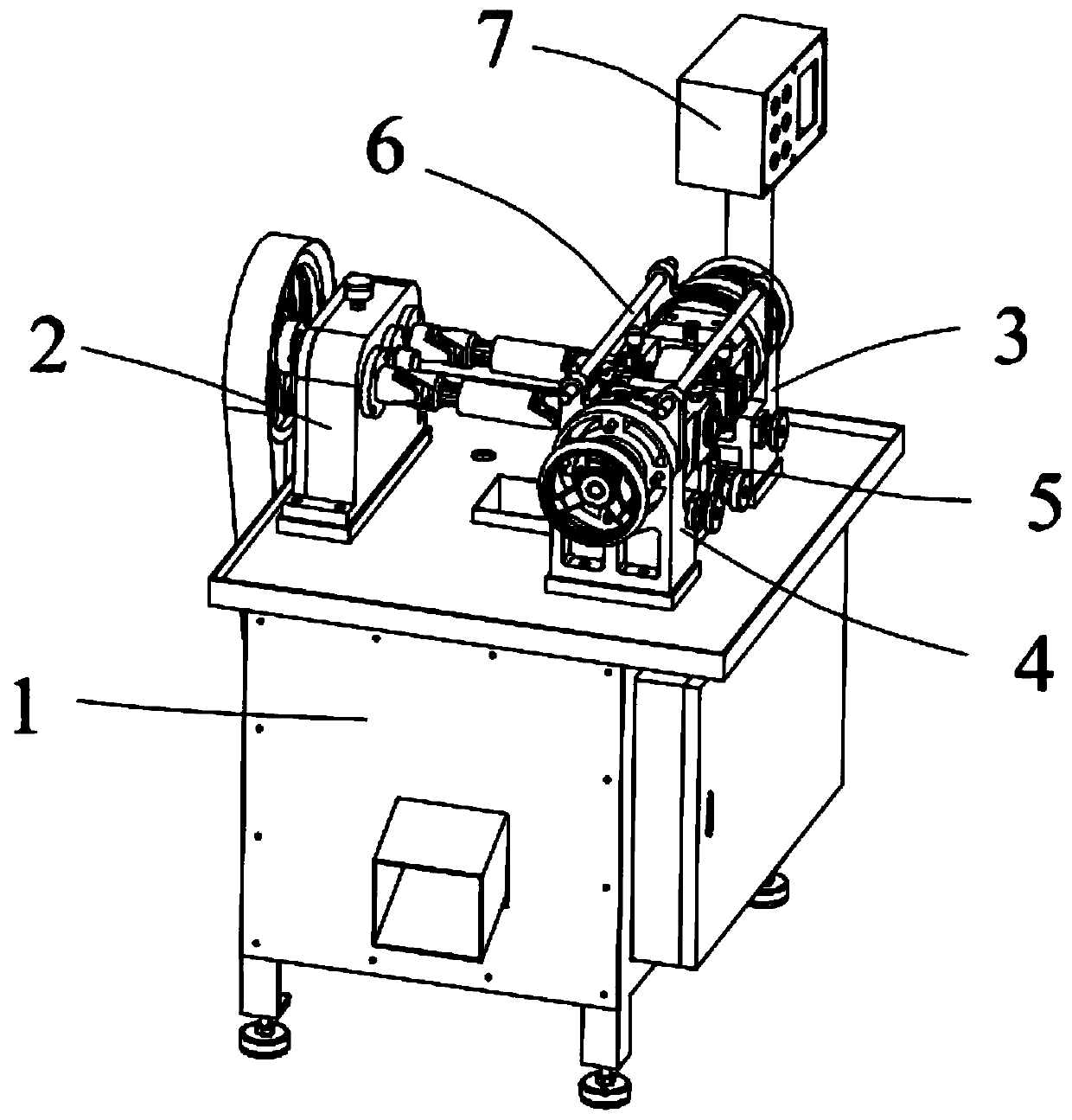
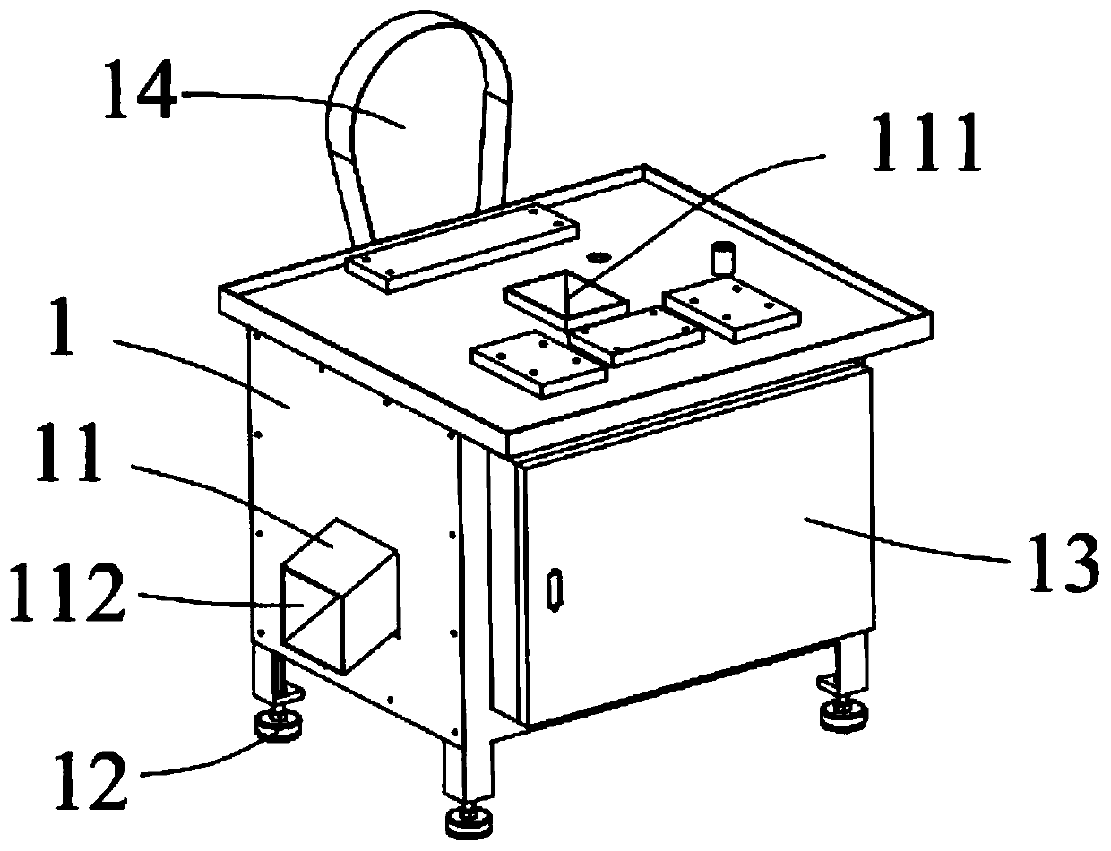
[0036] Please refer to figure 1 and 2Shown are the three-dimensional schematic diagram and the structural schematic diagram of the machine body of the straightening machine applied to the circular cross-section steel in the embodiment, respectively.

[0037] This embodiment provides a straightening machine applied to round-section steel, which is a device for straightening round-section steel, which includes a body 1, a reduction box device 2 installed on the body 1, and a first pressure wheel Device 3, the second pressure roller device 4 and the blade device 5, wherein the first pressure roller device 3, the second pressure roller device 4 and the blade device 5 are located on the same side of the reduction box device 2, and the blade device 5 is located on the first Between the pressure wheel device 3 and the second pressure wheel device 4 , the reduction box device 2 is connected to the first pressure wheel device 3 and the second pressure wheel device 4 respectively. Amo...


PUM


Abstract

The invention discloses a straightening machine applied to circular fracture surface steel. The straightening machine comprises a machine body and further comprises a speed reduction box device, a first pressing wheel device, a second pressing wheel device and a tool board device which are arranged on the machine body. The first pressing wheel device comprises a first installing base, a first rotation base, a first angle adjusting worm, a first distance adjusting lead screw, a first moving base, a straightening cam and a cam rotation shaft. The second pressing wheel device comprises a second installing base, a second rotation base, a second angle adjusting worm, a second distance adjusting lead screw, a second moving base, a straightening concave wheel and a concave wheel rotation shaft. The straightening cam of the arranged first pressing wheel device and the straightening concave wheel of the second pressing wheel device are utilized for cooperation for automatic straightening of thecircular fracture surface steel, the distance and the inclination angle between the straightening cam and the straightening concave wheel can be adjusted, and the straightening machine is applicableto different sizes of circular fracture surface steel and different angle straightening requirements.

Description

technical field [0001] The invention relates to the technical field, in particular to a straightening machine applied to round-section steel. Background technique [0002] In the processing of bearings or electrical shafts, steel with round sections is generally used as raw materials. During the production process, both ends of the steel with round sections need to be ground and embossed, and finally processed into the required bearings or electrical appliances. Axis products. However, steels with circular cross-sections are generally deformed due to collisions during storage or transportation when incoming materials are received, and deformed steels with circular cross-sections are prone to deformation during grinding and embossing processing. The processing effect is not up to standard, resulting in defective products, thereby reducing the overall quality of the product. [0003] In order to reduce the defect rate of products caused by the deformation of round-section st...

Claims


Application Information

Patent Timeline
Patent Type & Authority Patents(China)
IPC IPC(8): B21D3/05
CPCB21D3/05
Inventor 殷育宁赵术喜张攀邢豪罗振红王春红姜超
Owner 惠州市腾贸精密工业有限公司
Why Eureka
Try Eureka