Positioning and clamping drill jig

A technology for positioning clamps and drilling molds, which is applied in the direction of drilling molds for workpieces, etc., which can solve problems such as rolling displacement offset, workpiece damage, scrapping, etc., to prevent displacement changes, improve clamping efficiency, and fast clamping Effect

Pending Publication Date: 2019-04-26
ANHUI TECHN COLLEGE OF MECHANICAL & ELECTRICAL ENG
View PDF0 Cites 0 Cited by
  • Summary
  • Abstract
  • Description
  • Claims
  • Application Information

AI Technical Summary

Problems solved by technology

[0003] In view of the above-mentioned prior art, the purpose of the present invention is to overcome the inconvenience of the machining process caused by the rolling or displacement of workpieces with structures such as arcuate surfaces easily caused by the drilling jig in the prior art during the machining process. Even problems such as damage and scrapping of workpieces, so as to provide a positioning and clamping drilling template that can clamp workpieces of this structure, facilitate its positioning and drilling of radial apertures, etc.

Method used


Image

  • Positioning and clamping drill jig
  • Positioning and clamping drill jig
  • Positioning and clamping drill jig

Examples


Embodiment Construction

[0034] Specific embodiments of the present invention will be described in detail below in conjunction with the accompanying drawings. It should be understood that the specific embodiments described here are only used to illustrate and explain the present invention, and are not intended to limit the present invention.

[0035] In the present invention, unless stated to the contrary, the used orientation words such as "up, down, left, right, vertical, horizontal, horizontal, vertical" usually refer to the positional relationship under normal use.

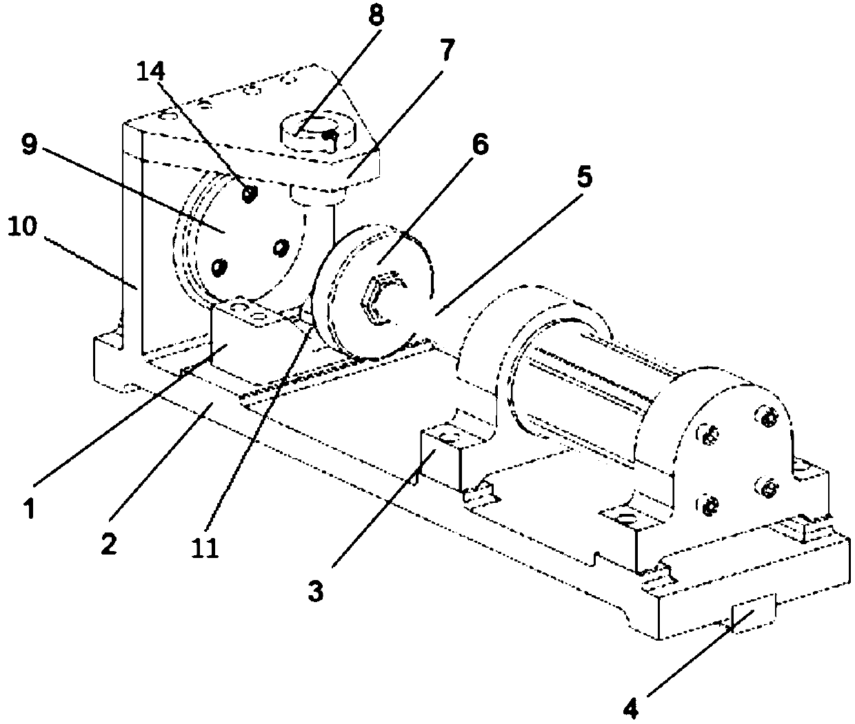
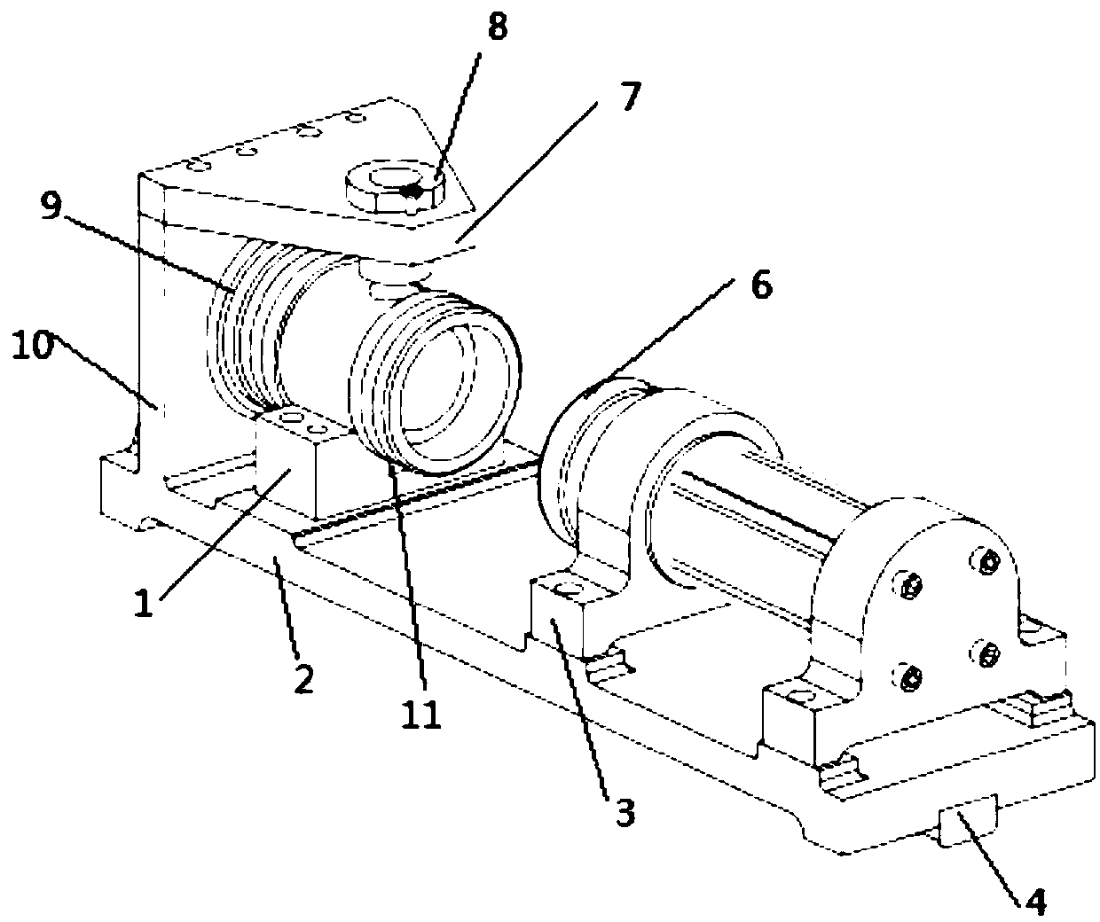
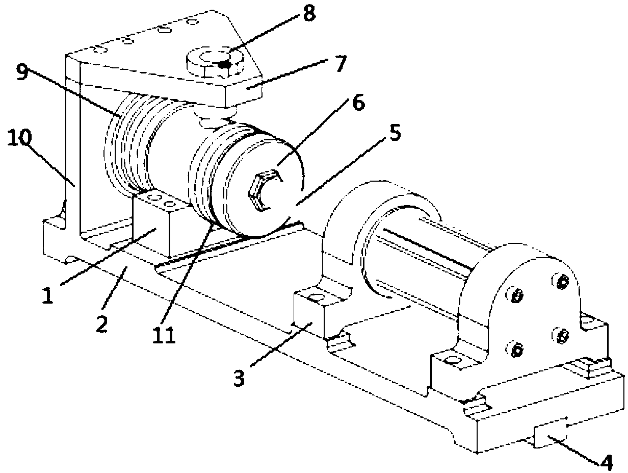
[0036] The invention provides a positioning and clamping drill form, wherein, as Figure 1-Figure 4 As shown, the positioning and clamping jig mold includes a base 2, a vertical plate 10, a clamping block 1, and a telescopic fastening mechanism arranged on the upper surface of the base 2 in sequence along the extension direction of the base 2, and a set The drill placement unit above the clamping block 1; wherein,

[0037] A first p...


PUM


Abstract

The invention discloses a positioning and clamping drill jig. The positioning and clamping drill jig comprises a base (2), and a vertical plate (10), a clamping block (1) and a telescopic fastening mechanism which are sequentially arranged on the upper surface of the base in the extending direction of the base, and a drill bit containing unit arranged above the clamping block. A first positioningpiece (9) is arranged on the side face, facing the telescopic fastening mechanism, in the vertical plate. The telescopic fastening mechanism at least comprises a telescopic unit and a second positioning piece (6) arranged on the telescopic unit and close to one side of the vertical plate, and the telescopic unit can drive the second positioning piece to be close to or away from the vertical plate;part of the upper surface of the clamping block is sunken inwards to form a clamping groove (11); and the drill bit containing unit at least comprises a placing plate (7) which is arranged above theclamping block and is provided with a through hole, and a drill bushing (8) which is detachably arranged on the through hole. The effects of clamping a machined part on the outer surface of the arc structure, facilitating positioning of the machined part and drilling the radial aperture of the machined part are achieved.

Description

technical field [0001] The invention relates to the field of drilling mold structures, in particular to positioning and clamping drilling molds. Background technique [0002] Drilling and other processing processes are very commonly used processing methods in production. During the processing process, problems such as the surface shape of the workpiece to be processed often have a certain radian, which causes problems such as deviation during the processing process, resulting in processing The inconvenience of the process, a little carelessness will easily cause the processing position to change during the processing, resulting in damage or even scrapping of the workpiece to be processed, which will bring great losses to the production cost. Contents of the invention [0003] In view of the above-mentioned prior art, the purpose of the present invention is to overcome the inconvenience of the machining process caused by the rolling or displacement of workpieces with struct...

Claims


Application Information

Patent Timeline
Patent Type & Authority Applications(China)
IPC IPC(8): B23B47/28
CPCB23B47/28B23B2247/12
Inventor 张国政周元枝刘顺
Owner ANHUI TECHN COLLEGE OF MECHANICAL & ELECTRICAL ENG
Why Eureka
Try Eureka