
Electronic parking system, vehicle comprising same and control method

An electronic parking and parking technology, which is applied to vehicle parts, brakes, transportation and packaging, etc., can solve the problems of low safety, achieve the effect of improving safety, ensuring response speed and smoothness, and improving safety

Pending Publication Date: 2019-04-26
NIO CO LTD
View PDF2 Cites 21 Cited by
  • Summary
  • Abstract
  • Description
  • Claims
  • Application Information

AI Technical Summary

Problems solved by technology

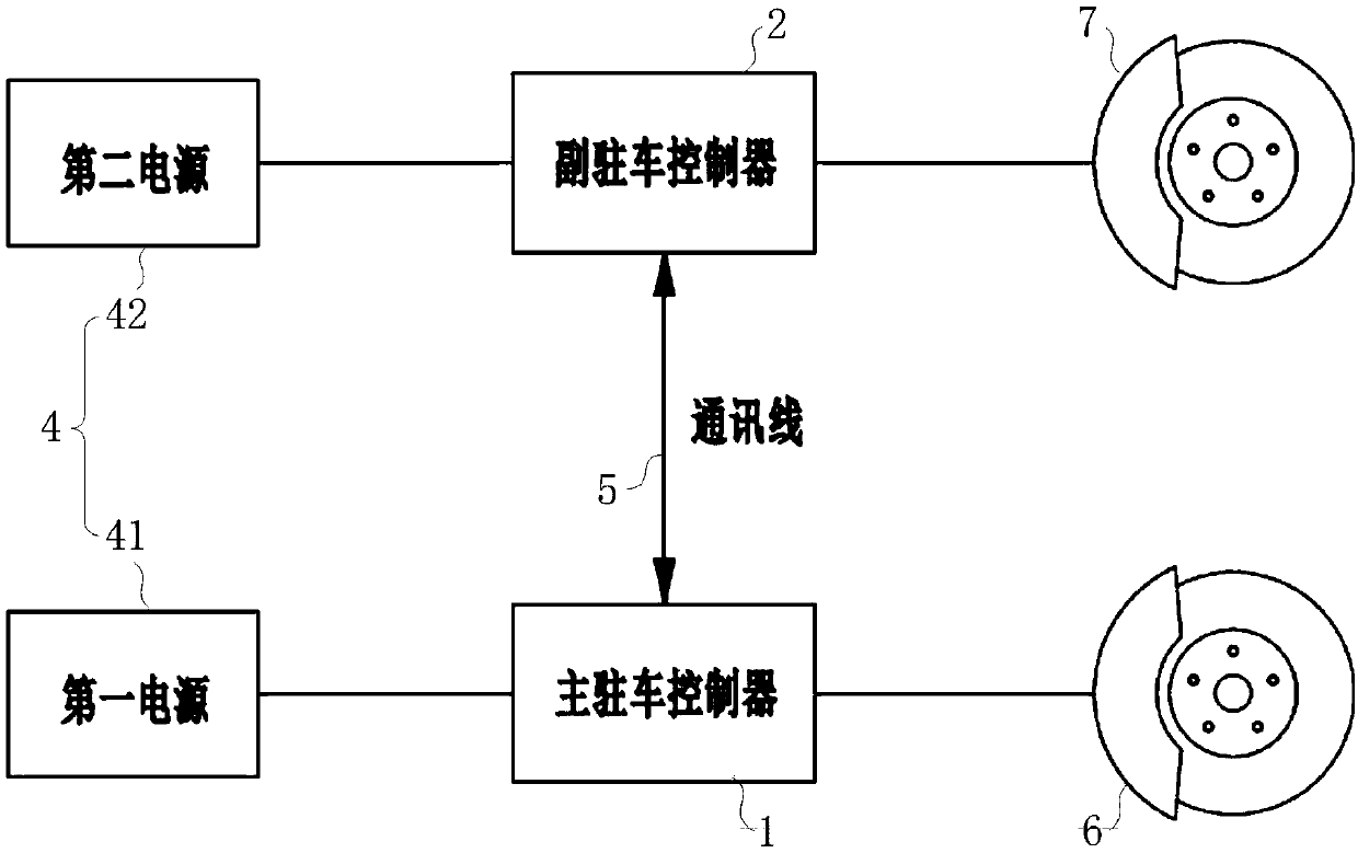
[0005] In order to solve the above-mentioned problems in the prior art, that is, in order to solve the problem of low safety existing in the existing electronic parking system, the present invention provides an electronic parking system, which includes: main parking The controller, the main parking controller is at least connected to the first wheel brake, and is used to receive a braking instruction and control the action of the first wheel brake based on the braking instruction; the auxiliary parking controller, the auxiliary parking controller The vehicle controller is at least connected to the second wheel brake, and is used to receive a braking command and control the action of the second wheel brake based on the braking command and the state signal of the master parking controller

Method used


Image

  • Electronic parking system, vehicle comprising same and control method
  • Electronic parking system, vehicle comprising same and control method
  • Electronic parking system, vehicle comprising same and control method

Examples


Embodiment 1

[0039] First refer to figure 1 , to describe the electronic parking system of the present invention. in, figure 1 It is a system block diagram of the electronic parking system in the first embodiment of the present invention.

[0040] Such as figure 1 As shown, in order to solve the problem of low security existing in the existing electronic parking system, the electronic parking system of the present invention mainly includes a main parking controller 1, an auxiliary parking controller 2 and a power supply unit 4, the main parking control device 1 and the first wheel brake 6 ( figure 1 The brake calipers in the middle) are connected to receive the brake command and control the action of the first wheel brake 6 based on the command; the auxiliary parking controller 2 is connected to the second wheel brake 7 and used to receive the brake command and control the action based on the command and the second wheel brake 7. The status signal of the main parking controller 1 contr...

Embodiment 2

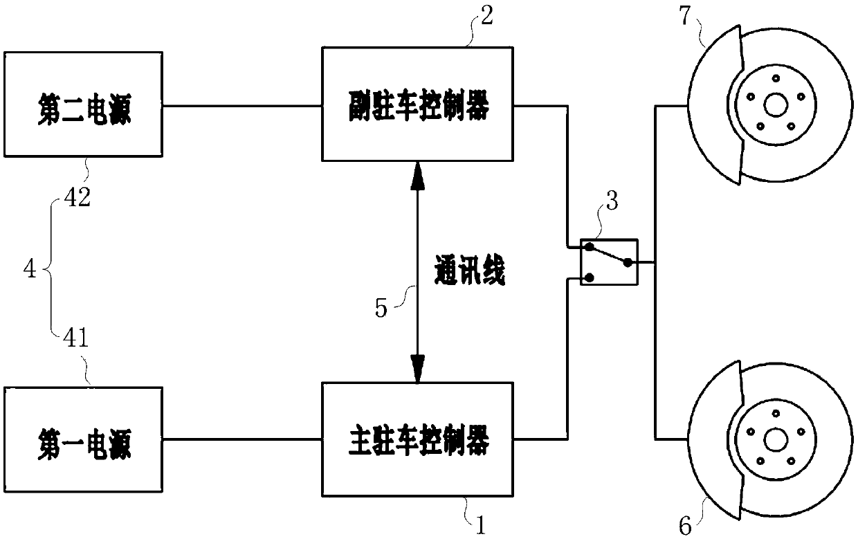
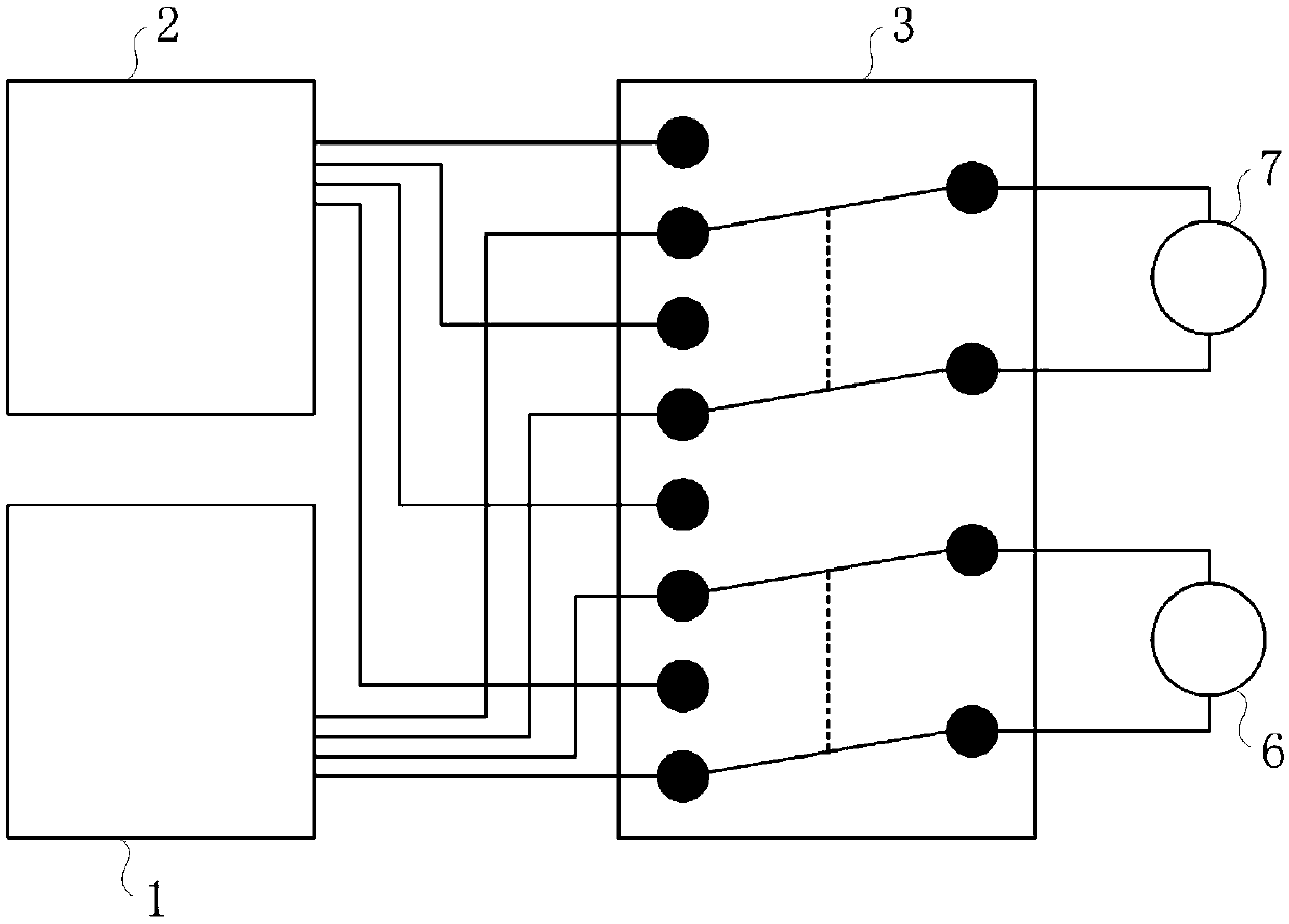
[0047] Refer below figure 2 with image 3 , to describe the second embodiment of the present invention. in, figure 2 It is a system block diagram of the electronic parking system in the second embodiment of the present invention; image 3 It is a schematic diagram of the connection of the switch in the second embodiment of the present invention.

[0048] Such as figure 2 As shown, in a possible implementation manner, on the basis of the first embodiment, the electronic parking system further includes a switch unit 3, and the main parking controller 1 communicates with the first wheel brake 6 and the second wheel brake 6 through the switch unit 3. The brake 7 is connected so as to constitute a first control path. The auxiliary parking controller 2 is simultaneously connected to the first wheel brake 6 and the second wheel brake 7 through the switch unit 3 to form a second control path. The switch unit 3 can act based on the received switching signal, so as to turn on t...

Embodiment 3

[0054] Refer below Figure 4 , to describe the third embodiment of the present invention. in, Figure 4 It is a system block diagram of the electronic parking system in the third embodiment of the present invention.

[0055] Such as Figure 4 As shown, in a possible implementation manner, on the basis of the second embodiment, the switch 31 can also be redundantly set, that is, the switch unit 3 includes two switches 31, and each switch 31 has a fixed The point end and the moving point end, the fixed point end includes a plurality of fixed points, the main parking controller 1 and the auxiliary parking controller 2 are respectively connected with different fixed points on the two switches 31, and the moving point end includes A plurality of moving points, the first wheel brake 6 and the second wheel brake 7 are respectively connected with a plurality of moving points on a changeover switch 31 .

[0056] Similar to Embodiment 3, in a possible implementation manner, still ta...


PUM


Abstract

The invention relates to the technical field of automobile braking, in particular to an electronic parking system, a vehicle comprising the same and a control method. The invention aims to solve the problem that an existing electronic parking system is low in safety. In order to achieve the purpose, the electronic parking system comprises a primary parking controller and a secondary parking controller, wherein the primary parking controller is at least connected to a first wheel brake for receiving a braking command and controlling the first wheel brake to act based on the braking command; andthe secondary parking controller is at least connected to a second wheel brake for receiving the braking command and controlling the second wheel brake to act based on the braking command and a stateinformation of the primary parking controller. By arranging two electronic controllers redundantly, the electronic parking system can improve the safety performance of the vehicle.

Description

technical field [0001] The invention relates to the technical field of automobile braking, in particular to an electronic parking system, a vehicle including the electronic parking system and a control method. Background technique [0002] Electrical Parking Brake (EPB for short) is a technology that realizes parking brake through electronic control. In the current traditional cars, the electronic parking system has gradually become the mainstream due to its advantages of convenient operation, reliability, and small space occupation of the car. Generally, the electronic parking main system adopts two structural forms: cable-type electronic parking system and caliper-integrated electronic parking system. Both structural forms of electronic parking systems realize vehicle parking by braking the rear wheels separately. rear braking. [0003] With the continuous development of automatic driving technology, driving safety is always an inevitable topic. In order to realize the h...

Claims


Application Information

Patent Timeline
Patent Type & Authority Applications(China)
IPC IPC(8): B60T13/74
CPCB60T13/741
Inventor 解双双乌伟民施永祥覃涛罗健李壮运王坤坤张同
Owner NIO CO LTD
Learn More