Mechanical hand device

A technology of manipulators and manipulator guide rails, applied in the direction of conveyor objects, transportation and packaging, furnaces, etc., can solve the problems of complex layout, large space occupation, and insufficient efficiency, and achieve the effect of extensive industrial value

Inactive Publication Date: 2019-04-26
BEIJING SEMICON EQUIP INST THE 45TH RES INST OF CETC
View PDF7 Cites 3 Cited by
  • Summary
  • Abstract
  • Description
  • Claims
  • Application Information

AI Technical Summary

Problems solved by technology

The substrate transfer is mainly completed by the substrate transfer manipulator. The existing subst

Method used


Image

  • Mechanical hand device
  • Mechanical hand device
  • Mechanical hand device

Examples


Embodiment 1

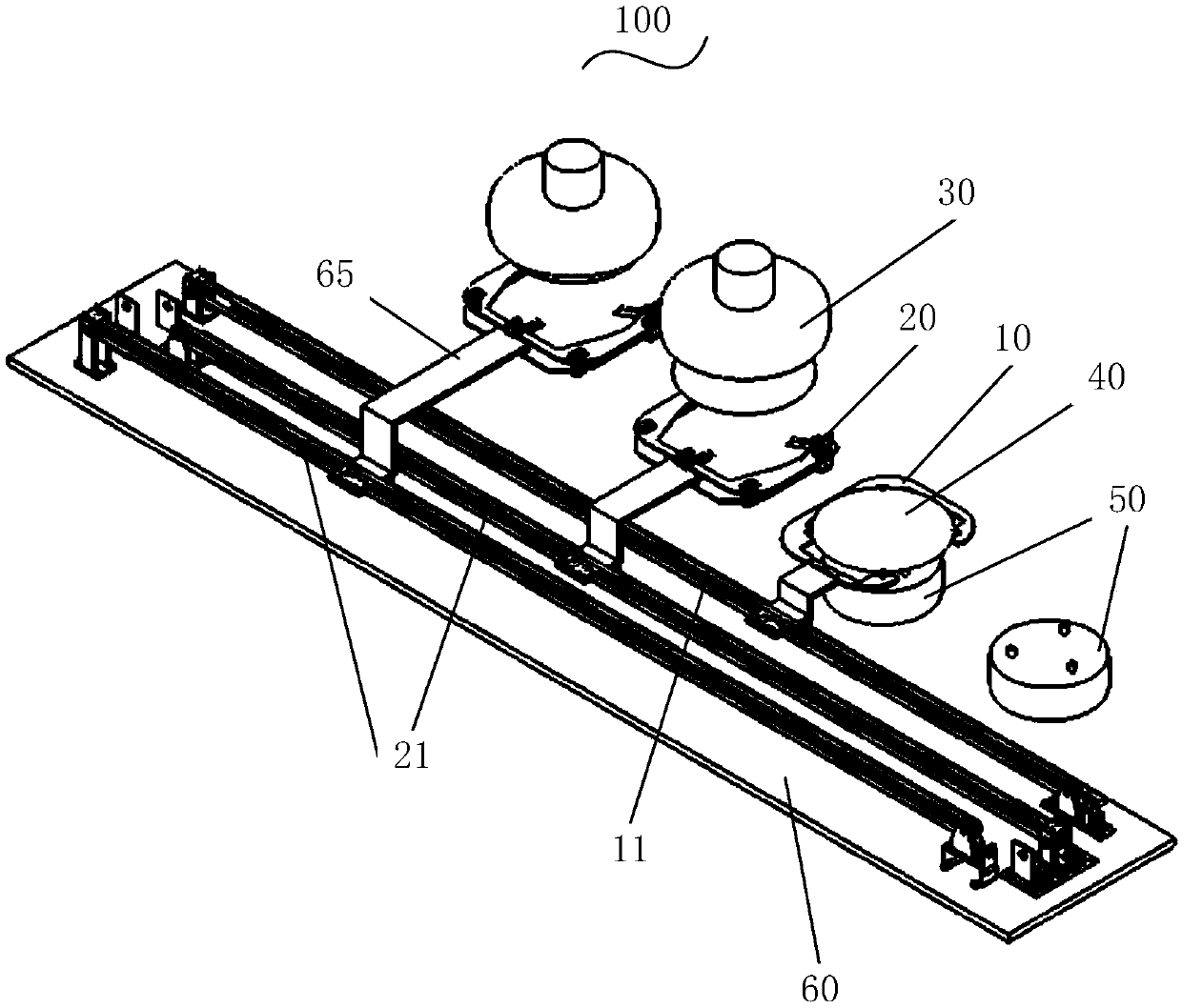
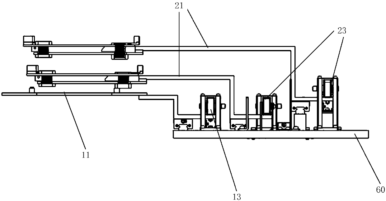
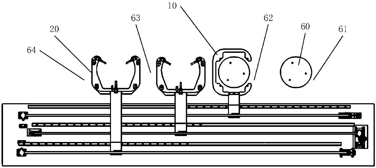
[0035] Such as Figure 1-6 .

[0036] The manipulator device 100 includes a positioning manipulator 10 for driving the external substrate 40 to move and place it at a preset position, and an external device for removing the substrate 40 from the preset position and processing it. An unloading manipulator 20 for unloading the substrate 40, the unloading manipulator 20 moves the substrate 40 to a preset station;

[0037]The manipulator device 100 also includes a positioning manipulator guide rail 11 for installing the positioning manipulator 10, an unloading manipulator guide rail 21 for installing the unloading manipulator 20, and the positioning manipulator guide rail 11 and the unloading manipulator guide rail 21 are parallel to each other. , the level of the unloading manipulator 20 is higher than the level of the positioning manipulator 10 .

[0038] above, such as image 3 , 4 As shown, the positioning manipulator 10 can place the substrate 40 at a preset position for ...


PUM


Abstract

The invention discloses a mechanical hand device. The mechanical hand device comprises a positioning mechanical hand for driving an external substrate to be moved and placed in a preset position and an unloading mechanical hand for unloading the substrate from an external device which takes down the substrate from the preset position and machines the substrate, wherein the unloading mechanical hand moves the substrate to a preset station. The mechanical hand device further comprises a positioning mechanical hand guide rail for installing the positioning mechanical hand and an unloading mechanical hand guide rail for installing the unloading mechanical hand, the positioning mechanical hand guide rail and the unloading mechanical hand guide rail are mutually parallel, and the horizontal plane height of the unloading mechanical hand guide rail is higher than that of the positioning mechanical hand guide rail. In the mechanical hand device, since the positioning mechanical hand guide railand the unloading mechanical hand guide rail are mutually parallel, and the positioning mechanical hand and the unloading mechanical hand are not in the same horizontal line, multiple working procedures can be simultaneously carried out, the efficiency is improved, and the space occupied by the mechanical hand device is reduced.

Description

technical field [0001] The invention relates to the technical field of mobile processing of CMP substrates, in particular, to a manipulator device. Background technique [0002] During CMP (Chemical mechanical polishing, chemical mechanical polishing) processing of substrates, due to equipment layout problems, it is necessary to transfer substrates between different stages to complete processing of substrates in different processes. Substrate transfer is mainly accomplished by a substrate transfer manipulator. The existing substrate transfer manipulator has a complex layout, takes up a large space, and is not efficient enough. Contents of the invention [0003] In view of this, the purpose of the robot device proposed by the present invention is to reduce the occupied space of the substrate robot device on the one hand, and to improve the transfer efficiency of the robot device on the other hand. [0004] Specifically, the present invention proposes the following specific...

Claims


Application Information

Patent Timeline
IPC IPC(8): B65G49/06B65G47/90
CPCB65G47/901B65G49/061
Inventor 李玉敏姚远尹影佀海燕费玖海
Owner BEIJING SEMICON EQUIP INST THE 45TH RES INST OF CETC
Why Eureka
Try Eureka