
Design method of super-resolution imaging system

A super-resolution imaging and design method technology, applied in optical components, optics, instruments, etc., can solve problems such as disregarding detector parameters, optical lens parameters, reconstruction algorithm parameter coupling relationship, reconstruction algorithm is difficult to perform, etc., to achieve optimal design , taking into account the effect of noise suppression

Active Publication Date: 2019-04-26
ACAD OF OPTO ELECTRONICS CHINESE ACAD OF SCI
View PDF6 Cites 0 Cited by
  • Summary
  • Abstract
  • Description
  • Claims
  • Application Information

AI Technical Summary

Problems solved by technology

In the design of traditional super-resolution imaging systems, the reconstruction algorithm design is insufficiently optimized for the inverse problem, resulting in the propagation and amplification of computational noise. In addition, the traditional design method does not consider the coupling relationship between detector parameters, optical lens parameters, and reconstruction algorithm parameters. Make it difficult for the reconstruction algorithm to perform ideally

Method used


Image

  • Design method of super-resolution imaging system
  • Design method of super-resolution imaging system
  • Design method of super-resolution imaging system

Examples


Embodiment Construction

[0018] The technical solutions in the embodiments of the present invention will be clearly and completely described below in conjunction with the accompanying drawings in the embodiments of the present invention. Obviously, the described embodiments are only some of the embodiments of the present invention, not all of them. Based on the embodiments of the present invention, all other embodiments obtained by persons of ordinary skill in the art without making creative efforts belong to the protection scope of the present invention.

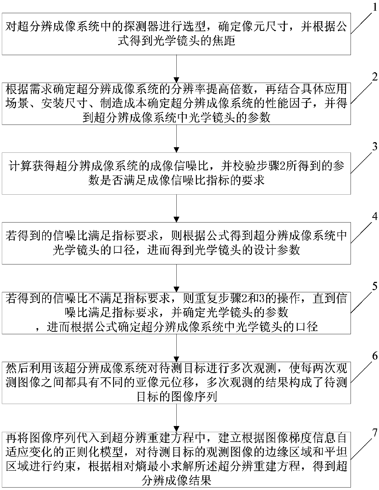
[0019] Embodiments of the present invention will be further described in detail below in conjunction with the accompanying drawings, as figure 1 Shown is a schematic flowchart of a design method of a super-resolution imaging system provided by an embodiment of the present invention, and the method includes:

[0020] Step 1. Select the detector in the super-resolution imaging system, determine the pixel size p, and obtain the focal length f of the o...


PUM


Abstract

The invention discloses a design method of a super-resolution imaging system, which comprises the following steps: firstly, selecting a detector in the super-resolution imaging system, determining a pixel size p, and obtaining a focal length f of an optical lens; determining the performance factor Eta of improvement of the multiple of the super-resolution imaging system according to the requirements, wherein the improvement of the multiple is shown in the description, and obtaining the F# number of the optical lens in the super-resolution imaging system; calculating to obtain the imaging signal-to-noise ratio SNR of the super-resolution imaging system, and checking whether or not the F# number meets the requirement of the imaging signal-to-noise ratio index; if the index requirement is met, obtaining the aperture D of the optical lens in the super-resolution imaging system, and further obtaining the design parameters of the optical lens; using the super-resolution imaging system for observing a target to be detected for a plurality of times and forming an image sequence yk of the target to be detected; substituting the image sequence yk into a super-resolution reconstruction equation, and solving the super-resolution reconstruction equation according to the minimum relative entropy to obtain a super-resolution imaging result. The design method of the super-resolution imaging system can make the system give full play to the advantages of super-resolution imaging, thereby achieving system-level optimization design.

Description

technical field [0001] The invention relates to the technical field of photoelectric imaging systems, in particular to a design method of a super-resolution imaging system. Background technique [0002] Geometric resolution is an important performance indicator of an optoelectronic imaging system. In traditional imaging systems, the geometric resolution of imaging is directly related to the focal length of the system optical lens and the pixel size of the imaging detector. The longer the focal length, the higher the resolution, and the smaller the pixel size. The higher the rate. However, with people's continuous pursuit of imaging quality, the development of high geometric resolution imaging systems is restricted by optical lenses and detectors, which are mainly reflected in: First, increasing the focal length increases the resolution while increasing the system size and weight, which not only limit the application of the system but also increase the manufacturing cycle an...

Claims


Application Information

Patent Timeline
IPC IPC(8): G02B27/58G02B27/00
CPCG02B27/0012G02B27/58
Inventor 谭政吕群波孙建颖王建威方煜张林
Owner ACAD OF OPTO ELECTRONICS CHINESE ACAD OF SCI
Learn More