Anti-caking crushing valve

An anti-caking and crushing device technology, applied in grain processing and other directions, can solve the problems of excessive fluctuation of powder conveying, affecting the normal flow rate of powder, and achieve the advantages of less flow interference, improved powder conveying efficiency, and improved crushing effect. Effect

Inactive Publication Date: 2019-04-30
NANTONG YAWEI MACHINERY MFG
View PDF3 Cites 0 Cited by
  • Summary
  • Abstract
  • Description
  • Claims
  • Application Information

AI Technical Summary

Problems solved by technology

[0005] The purpose of the present invention is to provide an anti-caking broken valve to solve the problem that the anti-caking rotor in the prior art breaks the agglomerates and affects the normal flow rate of the powder during the conveying process, which causes the occurrence of powder conveying problems. The problem of excessive volatility

Method used


Image

  • Anti-caking crushing valve
  • Anti-caking crushing valve
  • Anti-caking crushing valve

Examples


Embodiment Construction

[0027] The technical solution of the present invention is described in detail below through the examples, and the following examples are only exemplary and can only be used to explain and illustrate the technical solution of the present invention, rather than being interpreted as a limitation to the technical solution of the present invention.

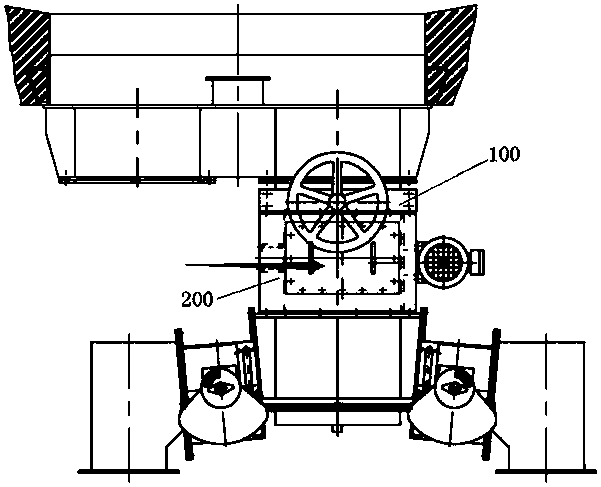
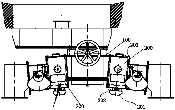
[0028] In this application, "front end" or "rear end" is a relative concept, not an absolute determination of the position. In this embodiment, the powder first passes through the control valve and then passes through the crushing device as an example. Therefore, the The direction of the control valve is the front end, and the crushing device is the rear end. Relative to the crushing device, the end close to the control valve is the front end, and the opposite end is the rear end.

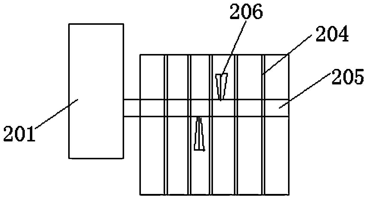
[0029] The application provides an anti-caking broken valve, such as Figures 1 to 3 As shown, it includes a control valve 100 and a crushing device 200 ar...


PUM


Abstract

The invention relates to an anti-caking crushing valve. The anti-caking crushing valve comprises a control valve and a crushing device arranged at the back end of the control valve. The crushing device comprises a shell body, a filter grid, a crushing rotor and a crushing motor; and the back end of the shell body is connected with a conveying pipe, and the front end of the shell body is connectedwith the back end of a shell of the control valve. According to the technical scheme, through the structure of the crushing device, especially the inclined arrangement of the filter grid and the eccentric arrangement of the crushing rotor, caked powder materials slip in the low direction of the filter grid after being in contactwith the filter grid, and the caked powder materials are relatively concentrated in the part with the low position of the filter grid; meanwhile, the eccentric arrangement of the crushing rotor reduces the interference to the powder flow rate on one side during rotation, the relatively concentrated caking powder materials can be crushed, and a motion acceleration for the crushing powder materials is provided to compensate the velocity lost in the early stage; and the crushing effect is improved, interference with the velocity of the materials in the process of conveying is little, and the conveying efficiency of the powder materials is improved.

Description

technical field [0001] The invention belongs to the technical field of material conveying, in particular to a crushing valve structure for preventing powder agglomeration. Background technique [0002] In the field of powder production, such as cement, pharmaceuticals, chemical fertilizers and other enterprises, there is a large amount of pipeline transportation or powder mixing processing. However, in the transportation process, in order to realize the control of the transportation volume, it is necessary to set up control valves and other components. While realizing the control, it is inevitable that the powder material will agglomerate near the control valve or adhere to the pipe wall and other parts. [0003] During the transportation of powder materials, if there is a pause, etc., the material will appear hardened, and such agglomerates will be crushed again under the action of external force, but if it is not dealt with, the agglomerates will become more and more diffi...

Claims


Application Information

Patent Timeline
Patent Type & Authority Applications(China)
IPC IPC(8): B02C18/12B02C18/16B02C23/08
CPCB02C18/12B02C18/16B02C23/08
Inventor 黄春英王进峰
Owner NANTONG YAWEI MACHINERY MFG
Why Eureka
Try Eureka