Eureka AIR delivers breakthrough ideas for toughest innovation challenges, trusted by R&D personnel around the world.

24G frequency modulation continuous wave level meter

A frequency-modulated continuous wave and level meter technology, which is applied in the field of level meters, can solve problems such as inconvenient angle adjustment, and achieve the effects of improving production efficiency, saving manpower, and convenient operation

Inactive Publication Date: 2019-04-30
ANHUI AUTOMATION INSTR
View PDF4 Cites 1 Cited by
  • Summary
  • Abstract
  • Description
  • Claims
  • Application Information

AI Technical Summary

Problems solved by technology

[0003] The purpose of the present invention is to solve the problem of inconvenient angle adjustment in the prior art, and propose a 24G frequency modulation continuous wave level gauge

Method used

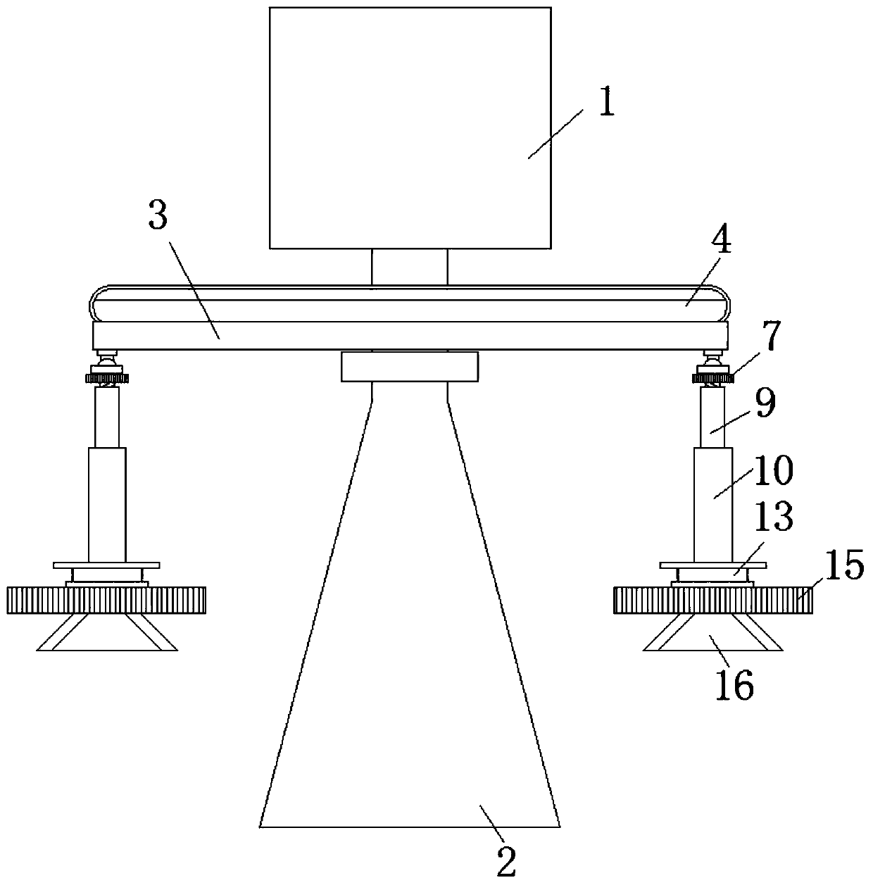
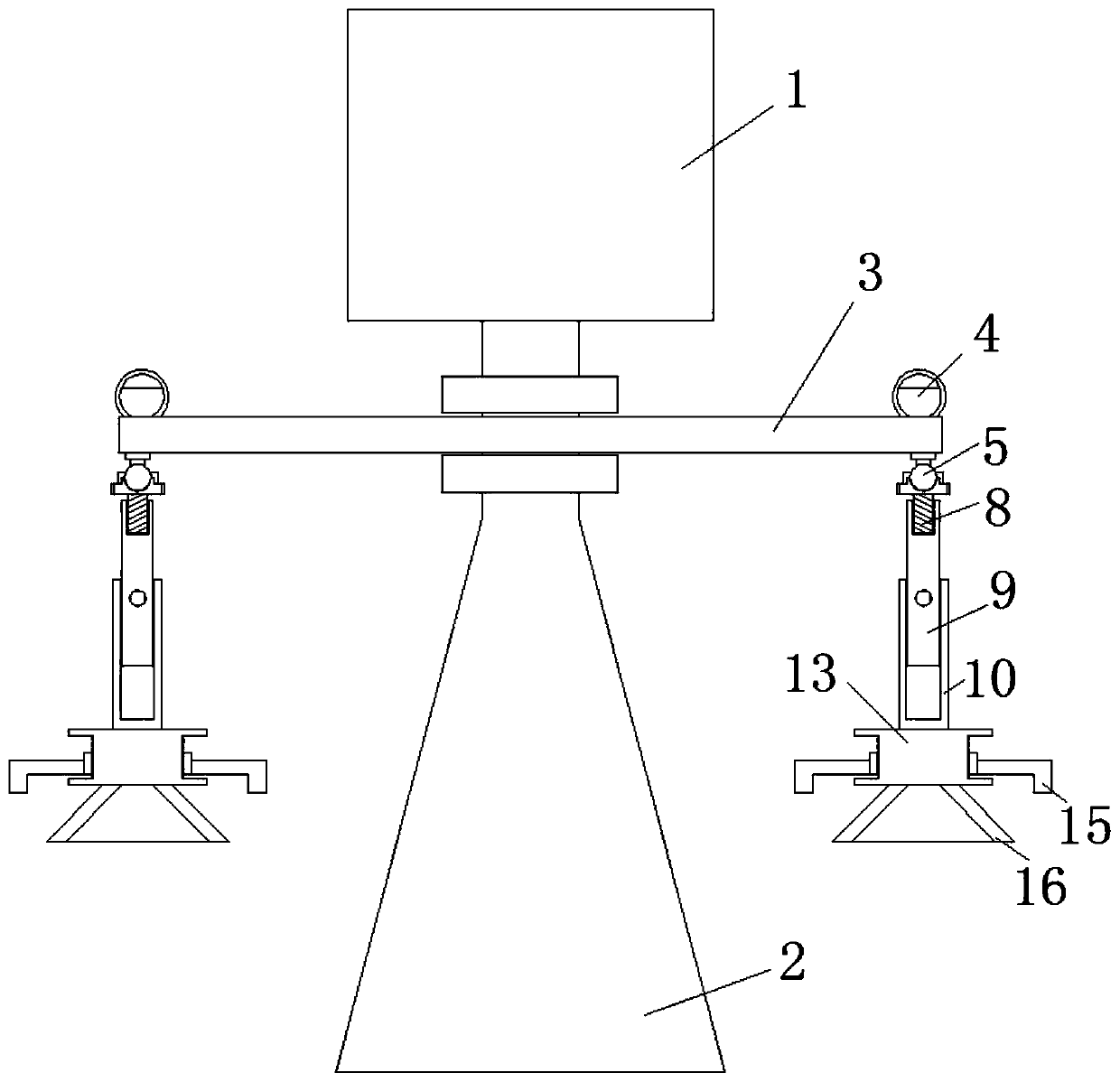

Image

  • 24G frequency modulation continuous wave level meter
  • 24G frequency modulation continuous wave level meter
  • 24G frequency modulation continuous wave level meter

Examples


Embodiment 1

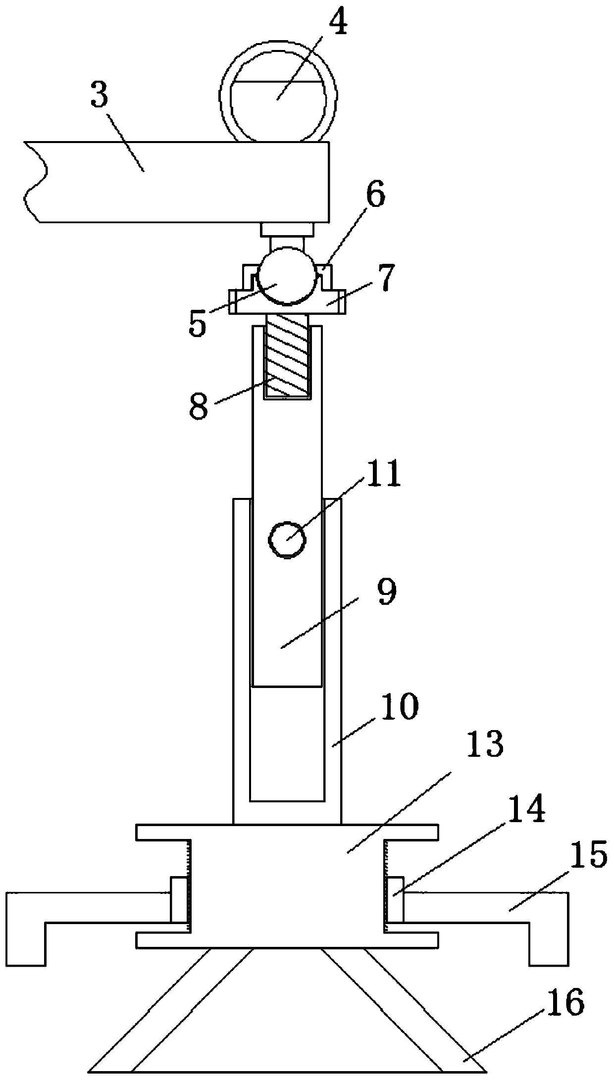
[0024] refer to Figure 1-4 , a 24G frequency modulation continuous wave level meter, including a meter body 1, a detection head 2 and a mounting plate 3, the meter body 1 is installed on the top side of the mounting plate 3, and the bottom end of the detection head 2 extends to the bottom side of the mounting plate 3 , the bottom side of the mounting plate 3 is fixedly welded with a swivel ball 5, and there are three swivel balls 5 that are equidistantly arranged, and the outer top of the swivel ball 5 is provided with an upper cover ring 6, and the bottom side of the swivel ball 5 is connected with a bottom sleeve 7. The top side of the bottom cover 7 is provided with grooves, the outer wall of the bottom cover 7 and the bottom inner wall of the upper cover ring 6 are provided with thread grooves, and the upper cover ring 6 is threaded on the top of the bottom cover 7, and the bottom cover 7 A threaded rod 8 is fixedly welded on the bottom side of the threaded rod 8, and the...

Embodiment 2

[0027] like Figure 1-4 As shown, this embodiment is basically the same as Embodiment 1. Preferably, the threaded post 13 is an I-shaped structure, and the threaded barrel 14 is threadedly disposed on the outside of the threaded post 13 .

[0028] In this embodiment, the rotation of the threaded cylinder 14 on the outside of the threaded column 13 adjusts the distance from the bottom end of the auxiliary fixing ring 15 to the outer wall of the silo.

Embodiment 3

[0030] like Figure 1-4 As shown, this embodiment is basically the same as Embodiment 1. Preferably, a horizontal observation tube 4 is connected to the top side of the mounting plate 3, and the horizontal observation tube 4 is an annular sealed transparent tube.

[0031] In this embodiment, when the outer wall of the silo is horizontal, it is convenient for people to level the mounting plate 3 .


PUM


Abstract

The invention discloses a 24G frequency modulation continuous wave level meter which comprises a watch body, a detection head and a mounting plate; the meter body is mounted on the top side of the mounting plate; the bottom end of the detection head extends to the bottom side of the mounting plate; three rotating balls are fixedly welded to the bottom side of the mounting plate; the three rotatingballs are uniformly arranged at equal intervals; an upper cover ring rotationally sleeves the outer side of the top end of each rotating ball; the bottom side of each rotating ball is connected witha bottom sleeve; a groove is formed in the top side of each bottom sleeve; threaded grooves are formed in the outer wall of each bottom sleeve and the inner wall of the bottom end of each upper coverring; each upper cover ring covers the top end of the corresponding bottom sleeve in a threaded mode; a threaded rod is fixedly welded to the bottom side of each bottom sleeve, and the bottom end of each threaded rod is sleeved with a telescopic auxiliary rod in a threaded mode. According to the invention, people can rapidly fix the level meter; the level meter is rapid and convenient to use and convenient to operate, people can rapidly and conveniently adjust the angle, manpower is saved, the production efficiency is improved, and the use requirements of people in production and life are met.

Description

technical field [0001] The invention relates to the technical field of level gauges, in particular to a 24G frequency modulation continuous wave level gauge. Background technique [0002] With the development of society and technology, level gauges are used more and more frequently, but the existing feeding equipment is observed through a transparent observation window or an observation port on the top, but there is no material around the observation port. The level meter is installed on a fixed flange, and re-drilling the hole will affect the stability of the entire device, and it is inconvenient. Therefore, the existing 24G FM continuous wave level meter is extremely inconvenient to install, and the angle of the observation hole is often It will be inclined to the bottom side of the silo, so when the level gauge is installed, the angle of the level gauge needs to be adjusted, while the existing 24G frequency modulation continuous wave level gauge can adjust the angle small...

Claims


Application Information

Patent Timeline
Patent Type & Authority Applications(China)
IPC IPC(8): G01F23/284
CPCG01F23/284
Inventor 柯正涛柯有玺俞春祥邬岳平井洪珍
Owner ANHUI AUTOMATION INSTR
Why Eureka
Eureka Blog
Learn More