Antenna leveling method and system

An antenna platform and antenna technology, applied in the field of antennas, can solve problems such as antenna linear scanning track sinking, achieve constant radiation gain and optimize measurement data.

Active Publication Date: 2019-04-30
BEIJING INST OF ENVIRONMENTAL FEATURES
View PDF3 Cites 5 Cited by
  • Summary
  • Abstract
  • Description
  • Claims
  • Application Information

AI Technical Summary

Problems solved by technology

The following problems were found during the test: First, due to the heavy weight of the front of the antenna platfo

Method used


Image

  • Antenna leveling method and system
  • Antenna leveling method and system
  • Antenna leveling method and system

Examples


Embodiment Construction

[0023] In order to make the purpose, technical solutions and advantages of the embodiments of the present invention clearer, the technical solutions in the embodiments of the present invention will be clearly and completely described below in conjunction with the drawings in the embodiments of the present invention. Obviously, the described embodiments It is a part of embodiments of the present invention, but not all embodiments. Based on the embodiments of the present invention, all other embodiments obtained by persons of ordinary skill in the art without making creative efforts belong to the protection scope of the present invention.

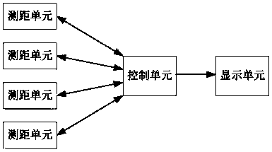
[0024] image 3 is a schematic diagram of the components of the antenna leveling system according to the embodiment of the present invention. Such as image 3 As shown, the antenna leveling system according to the embodiment of the present invention may include at least three distance measuring units. When in use, each distance measuring un...


PUM


Abstract

The invention relates to an antenna leveling method and system. One embodiment of the system comprises at least three distance measuring units; each of the at least three distance measuring units is arranged at the edge of the bottom surface of an antenna platform, and the signal transmitting direction of each distance measuring unit points to the ground; each distance measuring unit is used for acquiring the distance between the distance measuring unit and the ground; the distances acquired by the at least three distance measuring units are used for comparison; when the comparison results arethe same, it is represented that the antenna scanning surface is parallel to the ground; and when the comparison results are different, the antenna attitude is adjusted until the comparison results are the same. According to the embodiment, the antenna leveling can be realized by using the distance measuring units, and the problem of different radiation gains on the target caused by different antenna scanning beginning and end heights in the existing near-field electromagnetic test is solved.

Description

technical field [0001] The present invention relates to the technical field of antennas, in particular to an antenna leveling method and system. Background technique [0002] The near-field electromagnetic measurement system belongs to the vehicle-mounted measurement system, and the measurement method is that the antenna moves approximately horizontally to scan the target. The radiation gain of the electromagnetic wave in the direction vertical to the ground at the target has a cosine distribution. figure 1 It is a schematic diagram of the antenna radiation gain changing with height (that is, the distance between the antenna and the ground) (the abscissa is the radiation gain, and the ordinate is the height). It can be seen that the gain difference can reach 6.325db when the height difference is 0.2 meters, and the antenna height can be seen The difference will lead to the different radiation gain received by the target and finally affect the measurement data. The followin...

Claims


Application Information

Patent Timeline
IPC IPC(8): G01R29/10G01S15/08G01S17/08
CPCG01R29/10G01S15/08G01S17/08
Inventor 候浩浩高超吕鸣刘芳李常志
Owner BEIJING INST OF ENVIRONMENTAL FEATURES
Why Eureka
Try Eureka