Radio frequency device debugging method, device, equipment and system and storage medium

A technology of radio frequency device and debugging method, applied in the field of radio frequency, can solve the problems of guide debugging, low production efficiency and high cost, and achieve the effects of improving production efficiency, improving debugging accuracy and reducing production cost

Inactive Publication Date: 2019-04-30
徐晨阳
View PDF7 Cites 3 Cited by
  • Summary
  • Abstract
  • Description
  • Claims
  • Application Information

AI Technical Summary

Problems solved by technology

[0002] At present, the production and debugging of RF devices such as passive filters rely entirely or partially on manual debugging, which requires high debugging level for debugging technicians and difficult training, resulting in low production efficiency and high cost; the current auxiliary debugging method is through calculating filter S parameters Comparing the corresponding coupling matrix with the ideal coupling matrix or modifying the ideal coupling matrix to obtain a model of the influence of the bolt adjustment on the electrical performance of the filter
However, the calculation of the coupling matrix introduces errors. This method is only suitable for laboratory samples. There are many differences between the actual mass-produced products and the ideal design, and it is impossible to rely on the ideal coupling matrix to guide debugging.

Method used


Image

  • Radio frequency device debugging method, device, equipment and system and storage medium
  • Radio frequency device debugging method, device, equipment and system and storage medium
  • Radio frequency device debugging method, device, equipment and system and storage medium

Examples


Embodiment Construction

[0022] Embodiments of the technical solutions of the present invention will be described in detail below in conjunction with the accompanying drawings. The following examples are only used to illustrate the technical solutions of the present invention more clearly, and therefore are only examples, rather than limiting the protection scope of the present invention.

[0023] It should be noted that, unless otherwise specified, the technical terms or scientific terms used in this application shall have the usual meanings understood by those skilled in the art to which the present invention belongs.

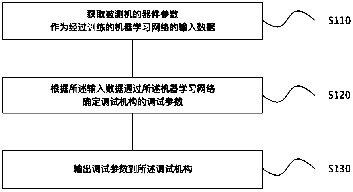
[0024] Such as figure 1 As shown, the implementation mode provided by Embodiment 1 of the present invention includes:

[0025] Step S110, obtaining the device parameters of the tested machine as the input data of the trained machine learning network, a specific implementation method is to obtain the device parameters of the passive coaxial cavity filter of the tested machine as the ...


PUM


Abstract

The invention discloses a radio frequency device debugging method, device, equipment and system and a storage medium. The method comprises the steps of acquiring device parameters of a tested machineto serve as input data of a trained machine learning network; determining debugging parameters of a debugging mechanism through the machine learning network according to the input data; and outputtingthe debugging parameters to the debugging mechanism, wherein the debugging mechanism is used for adjusting the tested machine according to the debugging parameters. The method disclosed by the invention realizes the purpose of automatic debugging, and achieves the effects of improving the production efficiency and reducing the production cost.

Description

technical field [0001] The invention relates to the field of radio frequency technology, in particular to a debugging method, device, equipment, storage medium and system of a radio frequency device. Background technique [0002] At present, the production and debugging of RF devices such as passive filters rely entirely or partially on manual debugging, which requires high debugging level for debugging technicians and difficult training, resulting in low production efficiency and high cost; the current auxiliary debugging method is through calculating filter S parameters The corresponding coupling matrix is ​​compared with the ideal coupling matrix or the ideal coupling matrix is ​​modified to obtain a model of the influence of the bolt adjustment amount on the electrical performance of the filter. However, the calculation of the coupling matrix introduces errors. This method is only suitable for laboratory samples. There are many differences between the actual mass-produce...

Claims


Application Information

Patent Timeline
Patent Type & Authority Applications(China)
IPC IPC(8): G01R31/28
CPCG01R31/2822
Inventor 徐晨阳
Owner 徐晨阳
Why Eureka
Try Eureka